Transmission device for capacitive coupling isolation transmission of pulse signals and corresponding transmission method

A technology of transmitting pulses and capacitive coupling, which is applied in the direction of logic circuit coupling device, output power conversion device, logic circuit connection/interface layout, etc.

Pending Publication Date: 2022-05-06
杭州欧佩捷科技有限公司
View PDF0 Cites 1 Cited by
  • Summary
  • Abstract
  • Description
  • Claims
  • Application Information

AI Technical Summary

Problems solved by technology

Due to the introduction of this low-pass filter, the speed of the rising and falling edges of the transmitted wide pulse is slowed down and the transmitted wide pulse cannot be reconstructed with as little distortion as possible

Method used


Image

  • Transmission device for capacitive coupling isolation transmission of pulse signals and corresponding transmission method
  • Transmission device for capacitive coupling isolation transmission of pulse signals and corresponding transmission method
  • Transmission device for capacitive coupling isolation transmission of pulse signals and corresponding transmission method

Examples


Embodiment 1

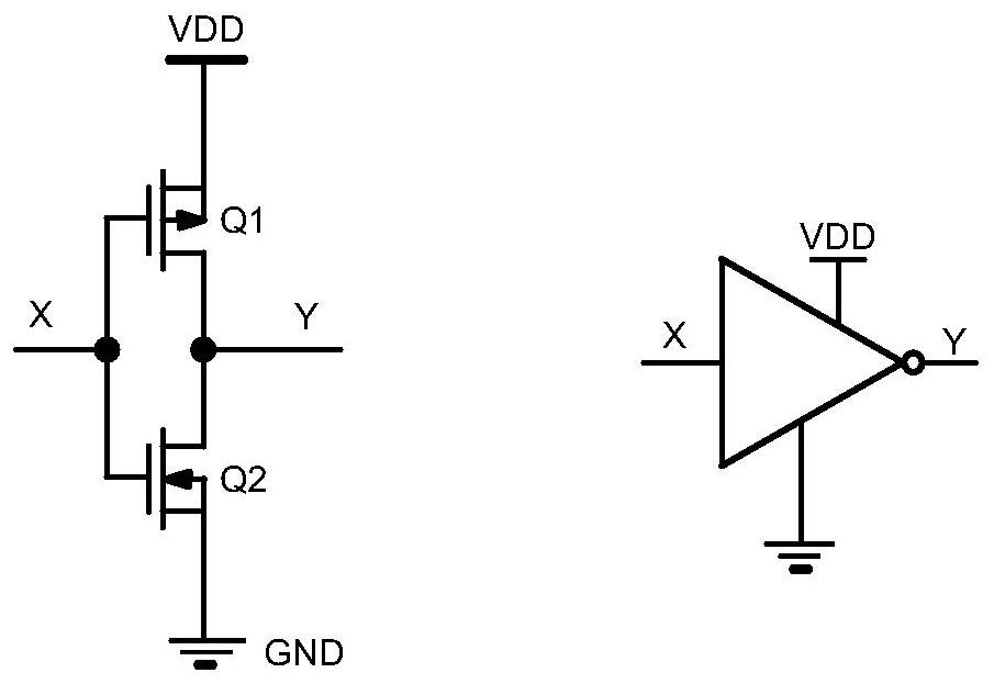
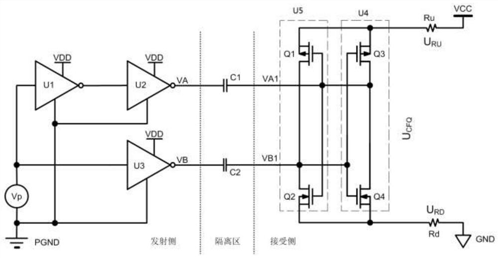
[0034] Embodiment 1, a kind of transmission device of capacitive coupling isolation transmission pulse signal, several CMOS logic inverters complete the pulse circuit diagram of transmitting various pulse widths through two high-voltage capacitors of small capacity value, as figure 2 shown.

[0035] It consists of a transmitting side, an isolation area, and a receiving side;

[0036] The transmit side includes three CMOS logic inverters U1, U2 and U3, and includes the pulse signal Vp required for transmit. The pulse signal Vp required to be transmitted by the transmitting side passes through three CMOS logic inverters U1, U2 and U3 to form mutually inverting VA and VB driving power supplies; the pulse signal Vp passes through U1 and U2 to obtain a driving voltage VA in phase with Vp, That is, Vp is input through the input terminal of U1, the output of U1 is connected to the input of U2, and the output terminal of U2 is VA; the pulse signal Vp generates the driving voltage VB...


PUM


Abstract

The invention discloses a transmission device for capacitive coupling isolation transmission of pulse signals. The transmission device comprises a transmitting side, an isolation region and a receiving side, the transmitting side comprises three CMOS (complementary metal oxide semiconductor) logic inverters U1, U2 and U3, the isolation region comprises small-capacitance high-voltage capacitors C1 and C2, and the receiving side comprises a bistable trigger which consists of a PMOS (P-channel metal oxide semiconductor) and an NMOS (N-channel metal oxide semiconductor) and has input and output at the same end, and two resistors Ru and Rd with the same resistance value; and the bistable flip-flop comprises a complementary metal oxide semiconductor (CMOS) logic phase inverter U5 and a CMOS logic phase inverter U4. The invention further discloses a transmission method for transmitting the pulse signals through capacitive coupling isolation by means of the transmission device. According to the invention, isolated transmission of pulse signals can be completed by a quite simple circuit.

Description

technical field [0001] The invention relates to a transmission device for capacitive coupling isolation transmission pulse signal and a corresponding transmission method. Background technique [0002] In an isolated output power supply, it is necessary to transmit a pulse signal from the primary side of the power supply to the secondary side, or from the secondary side to the primary side. There are several ways to accomplish the transmission of pulse signals from the primary side of the power supply to the secondary side, or from the secondary side to the primary side. One is to use optocoupler; the other is to use a pulse transformer; the third is to use two small-capacity high-voltage capacitors to complete. Due to the limitation of the response speed of the optocoupler, fast pulses cannot be transmitted using the optocoupler. Using a pulse transformer and two small value high voltage capacitors can transmit fast pulses but not wide pulses. For the transmission of wide...

Claims


Application Information

Patent Timeline
Patent Type & Authority Applications(China)
IPC IPC(8): H03K19/0175H02M1/00
CPCH03K19/017545H02M1/00
Inventor 翁大丰孙建中
Owner 杭州欧佩捷科技有限公司
Why Eureka
Try Eureka