Selective non-catalytic reduction denitration process
A non-catalytic and selective technology, applied in the field of flue gas denitrification, can solve the problems of increasing ammonia escape and increasing the amount of denitrification agent, and achieve the effect of solving ammonia escape, low cost and ultra-low emission
- Summary
- Abstract
- Description
- Claims
- Application Information
AI Technical Summary
Problems solved by technology
Method used
Image

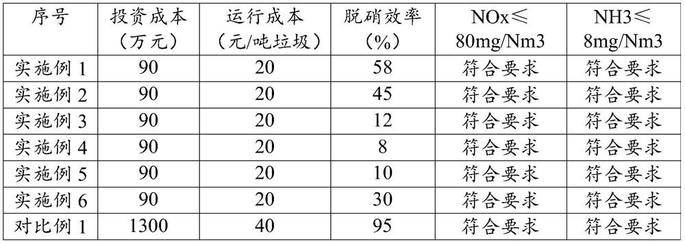

Examples
Embodiment 1
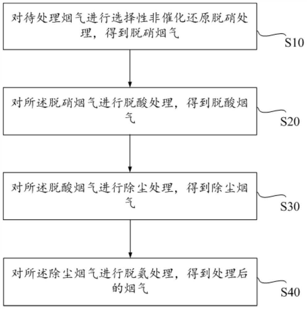
[0053] (1) Spray ammonia water (with a mass concentration of 20%) to the flue gas to be treated (at a temperature of 850° C.) with a compressed air pressure of 0.4 MPa, and after reducing the nitrogen oxides in the flue gas to be treated, denitrification flue gas is obtained .
[0054] (2) The denitrification flue gas is passed into the semi-dry reaction tower; the slaked lime is slurried at room temperature, and the slurry is atomized by a rotating atomizing disc (rotating speed 15000rph), and then sprayed at a high speed to form a liquid with a particle size of 20-501xm Drops are sprayed in the semi-dry reaction tower, fully mixed with the denitrification flue gas in the semi-dry reaction tower, and reacted at 150°C for 1s to remove SO 2 , HCl and HF to obtain deacidified flue gas.
[0055] (3) Provide a bag filter, the bag filter is provided with a plurality of filter bags; the deacidification flue gas is passed into the bag filter, and the deacidification flue gas passes ...
Embodiment 2
[0058] (1) Spray ammonia water (mass concentration: 15%) to the flue gas to be treated (at a temperature of 900° C.) with a compressed air pressure of 0.4 MPa, and after reducing the nitrogen oxides in the flue gas to be treated, denitrification flue gas is obtained .
[0059] (2) The denitrification flue gas is passed into the semi-dry reaction tower; the slaked lime is slurried at room temperature, and the slurry is atomized by a rotating atomizing disc (rotating speed 15000rph), and then sprayed at a high speed to form a liquid with a particle size of 20-501xm Drops are sprayed in the semi-dry reaction tower, fully mixed with the denitrification flue gas in the semi-dry reaction tower, and reacted at 150°C for 1s to remove SO 2 , HCl and HF to obtain deacidified flue gas.
[0060] (3) Provide a bag filter, the bag filter is provided with a plurality of filter bags; the deacidification flue gas is passed into the bag filter, and the deacidification flue gas passes through t...
Embodiment 3
[0063] (1) Spray ammonia water (with a mass concentration of 25%) to the flue gas to be treated (at a temperature of 950° C.) with a compressed air pressure of 0.4 MPa, and after reducing the nitrogen oxides in the flue gas to be treated, denitrification flue gas is obtained .
[0064] (2) The denitrification flue gas is passed into the semi-dry reaction tower; the slaked lime is slurried at room temperature, and the slurry is atomized by a rotating atomizing disc (rotating speed 15000rph), and then sprayed at a high speed to form a liquid with a particle size of 20-501xm Drops are sprayed in the semi-dry reaction tower, fully mixed with the denitrification flue gas in the semi-dry reaction tower, and reacted at 150°C for 1s to remove SO 2 , HCl and HF to obtain deacidified flue gas.
[0065] (3) Provide a bag filter, the bag filter is provided with a plurality of filter bags; the deacidification flue gas is passed into the bag filter, and the deacidification flue gas passes ...
PUM
 Abstract
Description
Claims
Application Information
 - R&D
- Intellectual Property
- Life Sciences
- Materials
- Tech Scout
- Unparalleled Data Quality
- Higher Quality Content
- 60% Fewer Hallucinations
Browse by: Latest US Patents, China's latest patents, Technical Efficacy Thesaurus, Application Domain, Technology Topic, Popular Technical Reports.
© 2025 PatSnap. All rights reserved.Legal|Privacy policy|Modern Slavery Act Transparency Statement|Sitemap|About US| Contact US: help@patsnap.com