Bouncing scooter
A scooter and bottom plate technology, used in bicycle accessories, bicycle brackets, bicycle safety equipment and other directions, can solve the problems of inertia and easy to tip forward, dump, unable to maintain balance, etc., to prevent secondary accidents, prevent left and right tilt, The effect of improving stability
- Summary
- Abstract
- Description
- Claims
- Application Information
AI Technical Summary
Problems solved by technology
Method used
Image
Examples
Embodiment 1
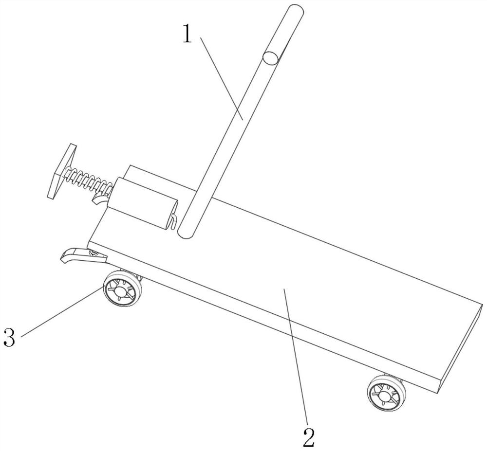
[0029] see Figure 1-Figure 5 , the present invention provides the following several technical solutions:
[0030] Option 1, the bouncing scooter, including the base plate 2 and the hand push rod 1 fixed on the upper end surface of the front side of the base plate 2, the four corners of the bottom surface of the base plate 2 are provided with wheels 3 for sliding the scooter, all the wheels 3 on the front and rear sides are fixed by The type suspension body is connected with the bottom plate 2. This scheme requires the user to jump up and bring the bottom plate up through the hand push rod 1 to realize the bouncing function, which requires higher skills for the user.
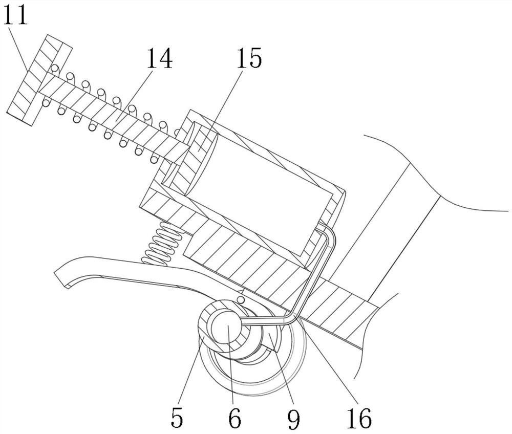
[0031] Option two, the bouncing scooter, including the base plate 2 and the hand push rod 1 fixed on the upper end surface of the front side of the base plate 2, the four corners of the bottom surface of the base plate 2 are provided with wheels 3 for sliding the scooter, and all the wheels 3 on the front and re...
Embodiment 2
[0044] The difference between this embodiment and embodiment 1 is that
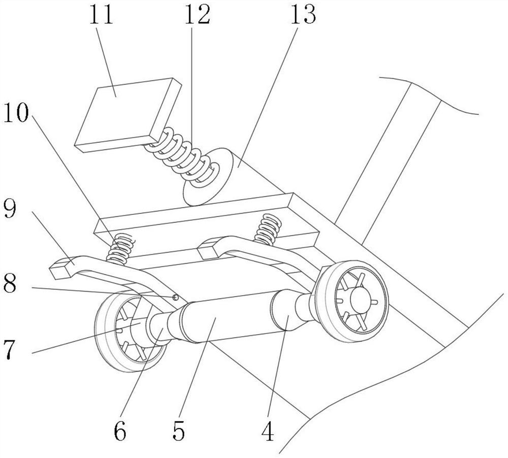
[0045] The support assembly includes a support rod 9, the side wall of the lower housing 21 is provided with a forward-inclining straight T-shaped chute, one end of the connecting shaft 8 is fixedly connected to the supporting rod 9, and the other end of the connecting shaft 8 is limited and slidable. On the T-shaped chute, a first spring 10 is arranged above the support rod 9 , the bottom end of the first spring 10 is fixedly connected with the support rod 9 , and the top end of the first spring 10 is fixedly connected with the bottom plate 2 . The connecting shaft 8 and the support rod 9 can only slide with the T-shaped chute.
[0046] During use, the contact surfaces between the truncated cone body 4 and the support rod 9 are all rough surfaces with a large friction coefficient. When the frustum of the cone 4 moved towards the direction of the support rod 9, the frustum of the cone 4 was in contact wi...
Embodiment 3
[0048] The difference between this embodiment and embodiment 2 is that
[0049] The side wall of the lower casing 21 is provided with an arc-shaped T-shaped chute inclined forward. The center of the arc-shaped T-shaped chute passes through the axis of the cone body 4 .
[0050] The connecting shaft 8 and the support rod 9 can only slide with the T-shaped chute.
[0051] During use, the contact surfaces between the truncated cone body 4 and the support rod 9 are all rough surfaces with a large friction coefficient. When the frustum of the cone 4 moved towards the direction of the support rod 9, the frustum of the cone 4 was in contact with the support rod 9. Since the frustum of the cone 4 rotated with the wheels 3, the support rod 9 was driven to swing forward. The support rod 9 touches the ground. The range where the bouncing scooter touches the ground is expanded, which can effectively prevent tilting. At the same time, during the swinging process of the support rod 9 fo...
PUM
 Abstract
Description
Claims
Application Information
 - R&D
- Intellectual Property
- Life Sciences
- Materials
- Tech Scout
- Unparalleled Data Quality
- Higher Quality Content
- 60% Fewer Hallucinations
Browse by: Latest US Patents, China's latest patents, Technical Efficacy Thesaurus, Application Domain, Technology Topic, Popular Technical Reports.
© 2025 PatSnap. All rights reserved.Legal|Privacy policy|Modern Slavery Act Transparency Statement|Sitemap|About US| Contact US: help@patsnap.com


