Double-medium layered injection flow control device and control method thereof
A technology for controlling device and injection flow, which is applied in the directions of measurement, production of fluid, and earth-moving drilling, etc. It can solve problems affecting workover efficiency, etc., and achieve the effect of wide application range, high temperature and pressure resistance level, and wide flow range.
- Summary
- Abstract
- Description
- Claims
- Application Information
AI Technical Summary
Problems solved by technology
Method used
Image

Examples
Embodiment 1
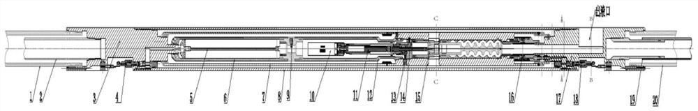
[0037] A control device for double-medium layered injection flow, including an upper layered injection structure, a control device, an adjustable flow assembly and a lower layered injection structure,
[0038] The upper layered injection structure includes an upper outer layer oil pipe 1, an inner layer oil pipe 2 and an upper joint 3, and the inner layer oil pipe 2 is installed in the upper outer layer oil pipe 1, forming a ring between the upper outer layer oil pipe 1 and the inner layer oil pipe 2 In the flow space, the tail end of the inner oil pipe 2 is threadedly connected with the upper joint 3, and the upper joint 3 is respectively provided with a first inner flow passage and a first outer flow passage through the upper joint 3, and the first outer flow passage The channel communicates with the annular flow space, the first inner flow channel communicates with the inner oil pipe 2, the annular flow space and the first outer flow channel form a water injection channel, a...
Embodiment 2
[0043] On the basis of Embodiment 1, a pressure gauge installation assembly is arranged between the tail end of the control unit cabin 6 and the head end of the motor sealing cabin 12, and a polymer injection string pressure gauge 9 is arranged on the pressure gauge installation assembly. Note The poly-column manometer 9 is electrically connected to the control unit 5 .
[0044] The tail end of the inner pipe 7 is provided with a water injection string pressure gauge 13 and a formation pressure monitoring device 14 respectively, and the water injection string pressure gauge 13 and the formation pressure monitoring device 14 are electrically connected to the control unit 5 respectively, and the current oil layer and the lower oil layer Separated by a packer, in order to monitor the front and rear pressures of the adjustable three-way valve 15 in real time and obtain the sealing state of the packer, the polymer injection string pressure gauge 9, the water injection string pressur...
Embodiment 3
[0050] Based on the second embodiment, the upper connector 3 is provided with an upper cable connector 4 for fixing and sealing cables, and the lower connector 17 is provided with a lower cable connector 18 for fixing and sealing cables.
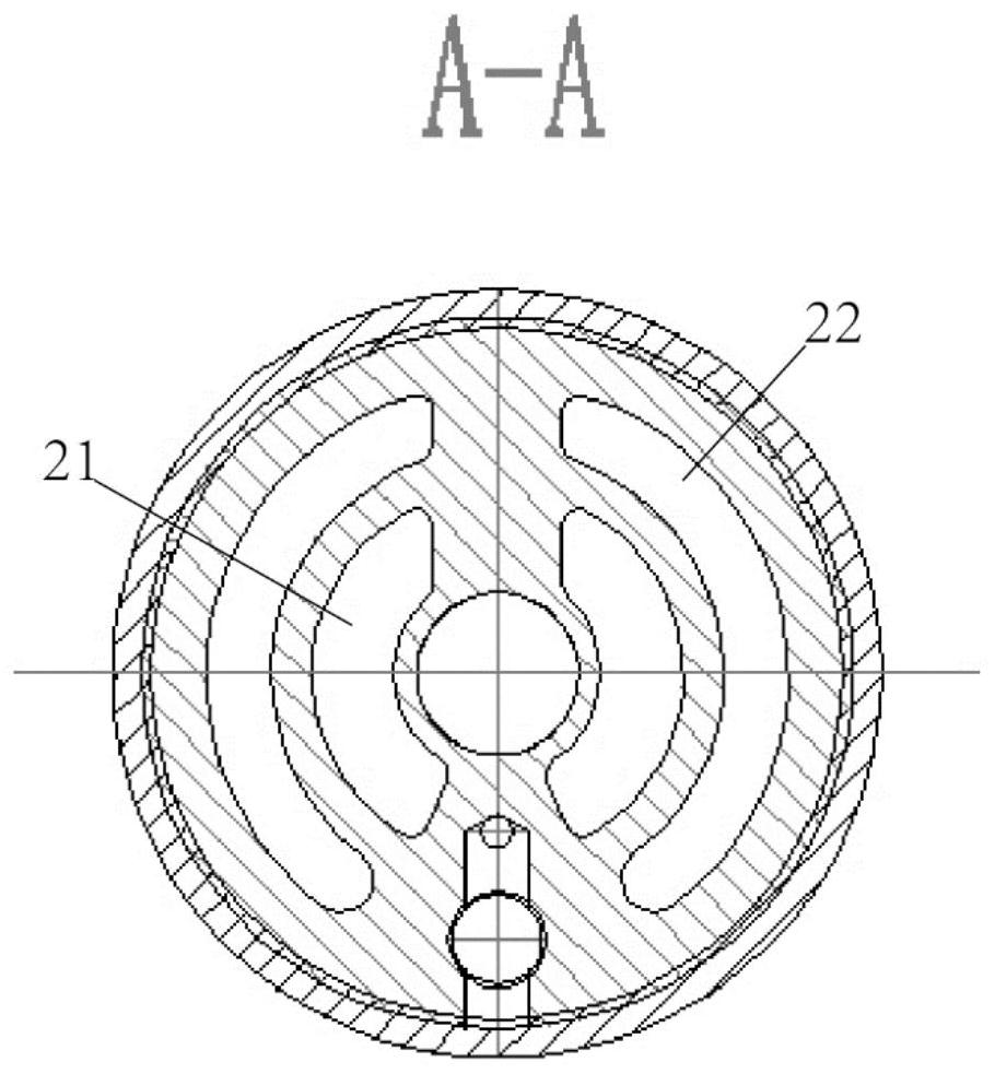
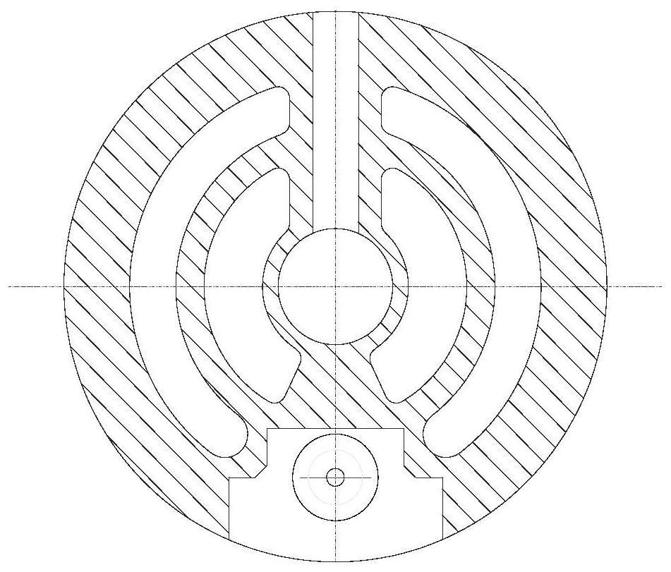
[0051] The minimum outer diameter of the control unit 5 is 95 mm, the equivalent diameters of the first inner overflow channel, the first outer overflow channel, the second inner overflow channel 21 and the second outer overflow channel 22 are at least 32 mm, and the liquid outlet The displacement is 400-550m 3 / d, the pressure difference that the control device for dual-media layered injection flow can withstand is 10-50Mpa, the working temperature of the control device for dual-media layered injection flow is 0-150°C, the control device for dual-media layered injection flow The tensile strength is 40-60t.
PUM
 Abstract
Description
Claims
Application Information
 - R&D
- Intellectual Property
- Life Sciences
- Materials
- Tech Scout
- Unparalleled Data Quality
- Higher Quality Content
- 60% Fewer Hallucinations
Browse by: Latest US Patents, China's latest patents, Technical Efficacy Thesaurus, Application Domain, Technology Topic, Popular Technical Reports.
© 2025 PatSnap. All rights reserved.Legal|Privacy policy|Modern Slavery Act Transparency Statement|Sitemap|About US| Contact US: help@patsnap.com