Cleaning device for range hood, fan cleaning device and range hood

A technology for cleaning devices and range hoods, which is applied to the components of pumping devices for elastic fluids, cleaning methods using liquids, and oil fume removal, etc. Weak strength and other problems, to achieve the effect of not affecting the performance of the fan, full coverage and efficient cleaning, and small modification of the original structure

Pending Publication Date: 2022-05-10
NINGBO FOTILE KITCHEN WARE CO LTD
View PDF2 Cites 0 Cited by
  • Summary
  • Abstract
  • Description
  • Claims
  • Application Information

AI Technical Summary

Problems solved by technology

[0003] At present, there are generally fixed holes on the spray pipe, and the number of holes is generally more than 3, but this cleaning method has the following disadvantages: First, when cleaning, steam or water is sprayed from the fixed nozzles, because there are limited Nozzles, so the flushing force at the interval between the nozzles is very weak, and the cleaning effect is not good; second, due to the large number of holes, the power of the steam generator or pump is constant, so the steam pressure or water pressure coming out of the nozzles is low. Correspondingly low and unstable, resulting in poor cleaning effect
[0005] However, first, for the above-mentioned first solution, it is necessary to set a long strip-shaped relief hole extending along the moving direction of the cleaning medium supply part on the volute, which will greatly modify the original structure of the fan, which will easily affect the performance of the fan. If the shielding part is set, there will be a problem that the viscous grease will stick to the shielding part after a long time, so that it cannot be opened or closed tightly; secondly, for the above-mentioned second scheme, the horizontal feeding type cleaning medium supply part requires an occupation of There is a lot of space, and the size of the current existing products is difficult to support such a large space; third, for the impeller, the oil stains in some parts are relatively stubborn, and often the oil stains in other positions cannot be completely removed. However, if the cleaning time is increased, it will cause a great waste of power consumption.

Method used


Image

  • Cleaning device for range hood, fan cleaning device and range hood
  • Cleaning device for range hood, fan cleaning device and range hood
  • Cleaning device for range hood, fan cleaning device and range hood

Examples


Embodiment 1

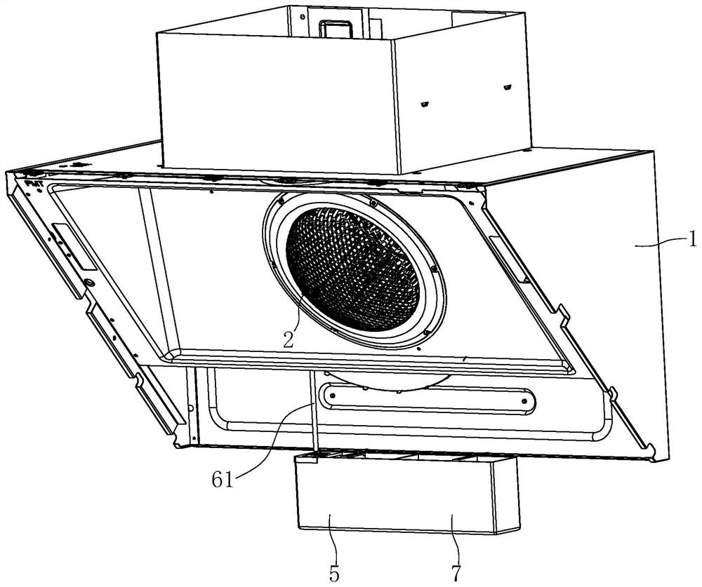
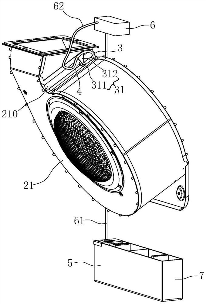
[0076] Such as Figure 1 to Figure 12 Shown is the first preferred embodiment of the range hood of the present invention. The range hood includes a casing 1 , a fan 2 , a cleaning medium supply part 3 , a driving device 4 , a water tank 5 , a steam generator 6 , a water receiving box 7 and a sensor 8 .

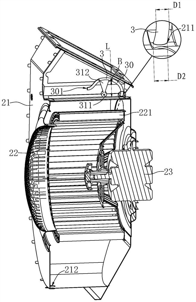
[0077] Wherein, the fan 2 is arranged in the casing 1 and includes a volute 21 , an impeller 22 arranged in the volute 21 and a driving member 23 for driving the impeller 22 to rotate. Such as image 3 As shown, the ring wall of the volute 21 is located at the position of the volute tongue 210 to open a relief hole 211, and the bottom of the volute 21 is provided with a drain hole 212; the impeller 22 is arranged at intervals along the circumferential direction with a plurality of axially extending Blade 221.

[0078] The cleaning medium supply part 3 is tubular, and has a front section, a middle section and a rear section successively along the flow direction of the cleani...

Embodiment 2

[0177] Such as Figure 13 Shown is the second preferred embodiment of the range hood of the present invention. The difference with Example 1 is:

[0178] In this example, if Figure 13 As shown, in the non-working state, the end face of the piercing portion 30 faces the relief hole 211, and the outlet 302 of the piercing portion 30 is located on the adjacent side wall of the end face, so that in the non-working state, the volute inside the The airflow of 21 is no longer easy to rush to the outlet 302 of the piercing part 30 through the relief hole 21 to cause its blockage.


PUM


Abstract

The invention discloses a cleaning device for a range hood, the cleaning device comprises a cleaning medium supply piece (3), the cleaning medium supply piece (3) comprises a moving part and an outlet (302) which is arranged on the moving part and is used for ejecting a cleaning medium, and the cleaning device is characterized in that the moving part is arc-shaped; the cleaning device further comprises a driving device (4), the power output end of the driving device is in transmission connection with the moving part, and the driving device is used for driving the whole moving part to swing. The invention further discloses a fan cleaning device applying the cleaning device and an extractor hood. Compared with the prior art, the cleaning device is small in occupied space and wide in cleaning range.

Description

technical field [0001] The invention relates to the technical field of kitchen equipment, in particular to a cleaning device for a range hood, a blower cleaning device and a range hood. Background technique [0002] With the continuous improvement of range hood self-cleaning technology, steam cleaning or water cleaning has been widely used in the self-cleaning field of range hoods. The basic principle is to generate steam by a steam generator or pump water to transport steam or water To the nozzle at the end of the spray pipe, steam or water is sprayed quickly from the nozzle to wash the impeller and volute for cleaning. [0003] At present, there are generally fixed holes on the spray pipe, and the number of holes is generally more than 3, but this cleaning method has the following disadvantages: First, when cleaning, steam or water is sprayed from the fixed nozzles, because there are limited Nozzles, so the flushing force at the interval between the nozzles is very weak, ...

Claims


Application Information

Patent Timeline
Patent Type & Authority Applications(China)
IPC IPC(8): F04D29/70F24C15/20B08B3/02
CPCF04D29/703F04D29/705F24C15/2057F24C15/2021B08B3/022B08B2203/0217
Inventor 王发银王亚男韩国强张岩茅忠群诸永定
Owner NINGBO FOTILE KITCHEN WARE CO LTD
Why Eureka
Try Eureka