Automatic measuring device for moisture content of wood
A measuring device and moisture content technology, applied in wood testing, material inspection products, etc., can solve the problems of manual handling, low product quality, waste of manpower and material resources, etc., to save manpower, improve environmental protection performance, and prevent wood from falling Effect
- Summary
- Abstract
- Description
- Claims
- Application Information
AI Technical Summary
Problems solved by technology
Method used
Image
Examples
Embodiment 1
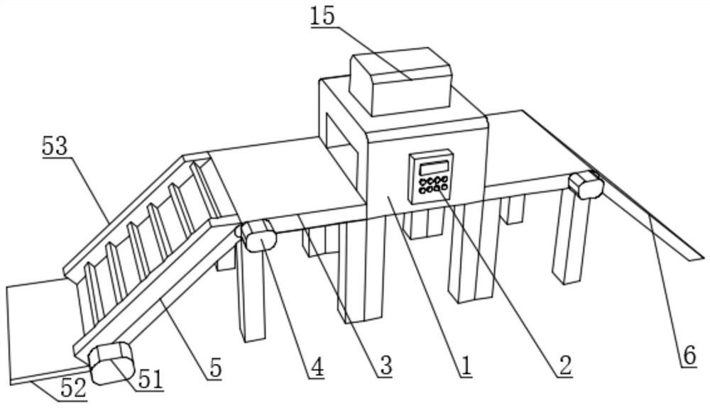
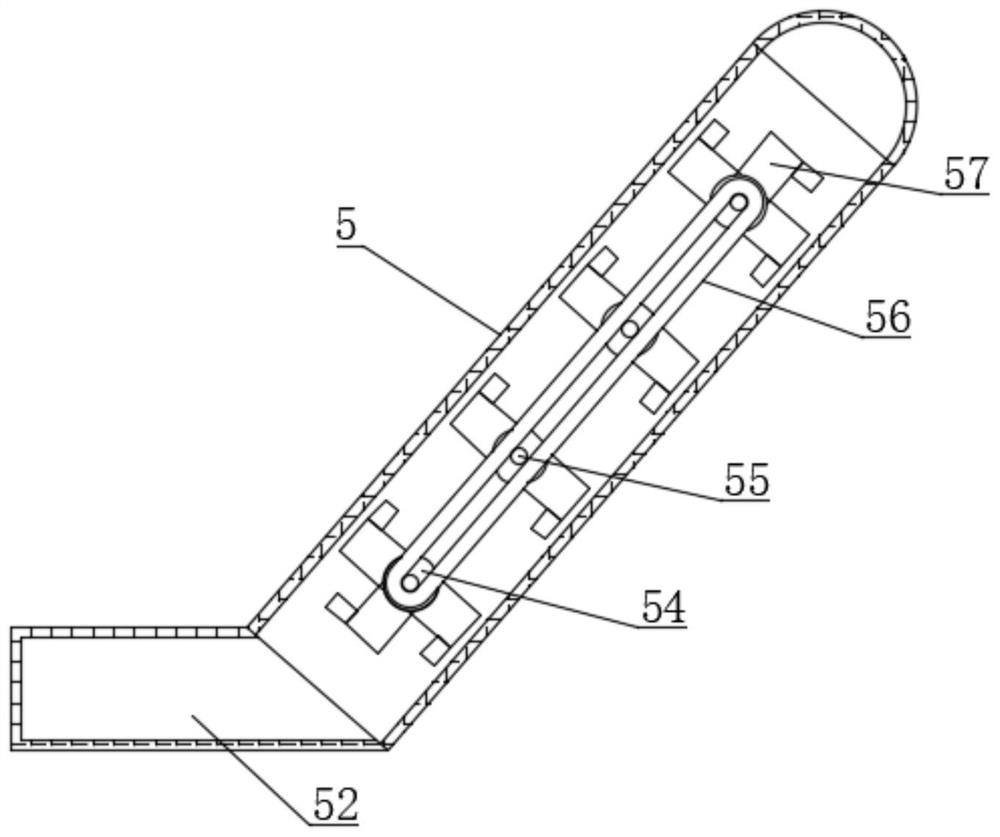
[0041] Such as Figure 1-5As shown, the present invention provides a kind of wood moisture content automatic measuring device, a kind of wood moisture content automatic measuring device, comprises measuring device body 1, and the outer surface of measuring device body 1 is fixedly installed with control module 2, and measuring device body 1 Conveyor belts 3 are arranged on both sides, one side of the conveyor belt 3 is fixedly connected with the first motor 4, one end of one conveyor belt 3 is fixedly connected with the feed end 5, and one end of the other conveyor belt 3 is fixedly installed with the discharge end 6, the measuring device body There are detection channels 11 on both sides of the inside of 1, and an accommodating chamber 12 is arranged inside the measuring device body 1, and a first telescopic rod 13 is fixedly installed inside the accommodating chamber 12, and the output end of the first telescopic rod 13 is fixed A wood moisture meter 14 is connected, the out...
Embodiment 2
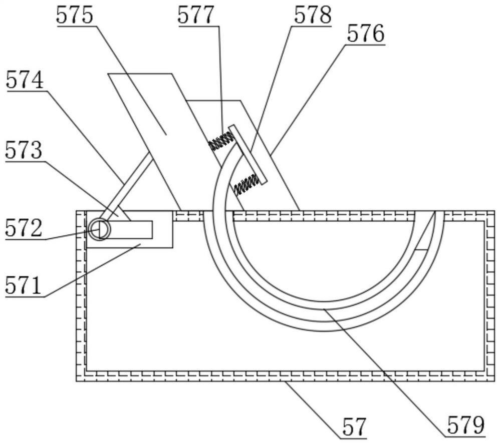
[0044] Such as Figure 1-5 As shown, on the basis of Embodiment 1, the present invention provides a technical solution: preferably, the top of the blocking mechanism 57 is provided with a chute 571, and the inside of the chute 571 is movably installed with a slider 572, and the top of the slider 572 A triangular limiting block 573 is fixedly installed, one side of the triangular limiting block 573 is fixedly connected with a support rod 574, one end of the supporting rod 574 is fixedly connected with the top of the slider 572, and the other end of the supporting rod 574 is fixedly connected with a blocking block 575 , the bottom of the blocking block 575 is fixedly connected to the top of the blocking mechanism 57, a buffer block 576 is fixedly installed on one side of the blocking block 575, a spring 577 is fixedly installed inside the buffer block 576, and a rebound plate 578 is fixedly connected to one end of the spring 577, One side of the resilient plate 578 is fixedly co...
Embodiment 3
[0047] Such as Figure 1-5 As shown, on the basis of Embodiment 1, the present invention provides a technical solution: preferably, a collection box 15 is movably installed on the top of the measuring device body 1, and a second telescopic rod is fixedly installed on the top of the inner wall of the accommodating chamber 12. 16. The output end of the second telescopic rod 16 is fixedly connected with a second motor 17, the output end of the second motor 17 extends to the outside of the accommodation chamber 12, and the output shaft of the second motor 17 is fixedly connected with a fixed drill bit 18, which accommodates The bottom of the inner wall of the storage chamber 12 is fixedly equipped with an exhaust fan 19, the output end of the exhaust fan 19 extends to the outside of the accommodating chamber 12 and is close to the output end of the second motor 17, and the other end of the exhaust fan 19 extends to the collection box 15 Inside, the fixed drill bit 18 includes a dr...
PUM
 Abstract
Description
Claims
Application Information
 - R&D
- Intellectual Property
- Life Sciences
- Materials
- Tech Scout
- Unparalleled Data Quality
- Higher Quality Content
- 60% Fewer Hallucinations
Browse by: Latest US Patents, China's latest patents, Technical Efficacy Thesaurus, Application Domain, Technology Topic, Popular Technical Reports.
© 2025 PatSnap. All rights reserved.Legal|Privacy policy|Modern Slavery Act Transparency Statement|Sitemap|About US| Contact US: help@patsnap.com


