
A device and method for accelerated aging reliability test of chip atomic clock

A chip atomic clock and accelerated aging technology, which is applied in the direction of adjustment devices, clocks, clocks, etc., can solve the problems of high cost and low efficiency of reliability testing, and achieve the effect of saving material costs, saving test time costs, and improving detection efficiency.

Active Publication Date: 2022-08-02
中科启迪光电子科技(广州)有限公司
View PDF9 Cites 0 Cited by
  • Summary
  • Abstract
  • Description
  • Claims
  • Application Information

AI Technical Summary

Problems solved by technology

[0005] For this reason, the present invention provides an accelerated aging reliability test device and method for chip atomic clocks to solve the problems of low reliability test efficiency and high cost of existing chip atomic clocks

Method used


Image

  • A device and method for accelerated aging reliability test of chip atomic clock
  • A device and method for accelerated aging reliability test of chip atomic clock
  • A device and method for accelerated aging reliability test of chip atomic clock

Examples


Embodiment 1

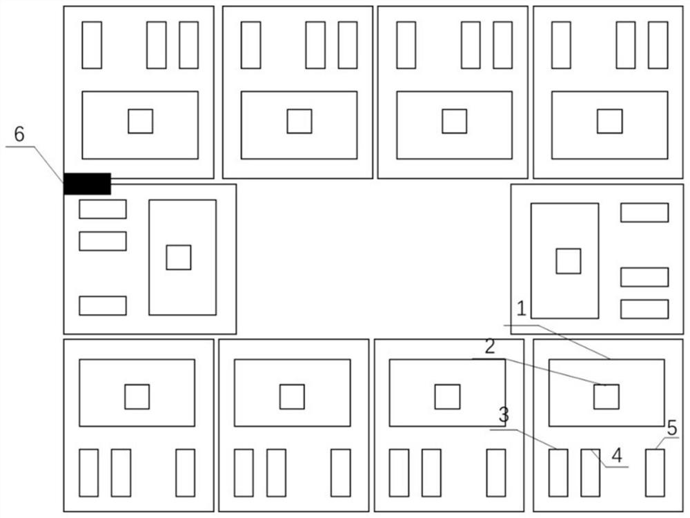
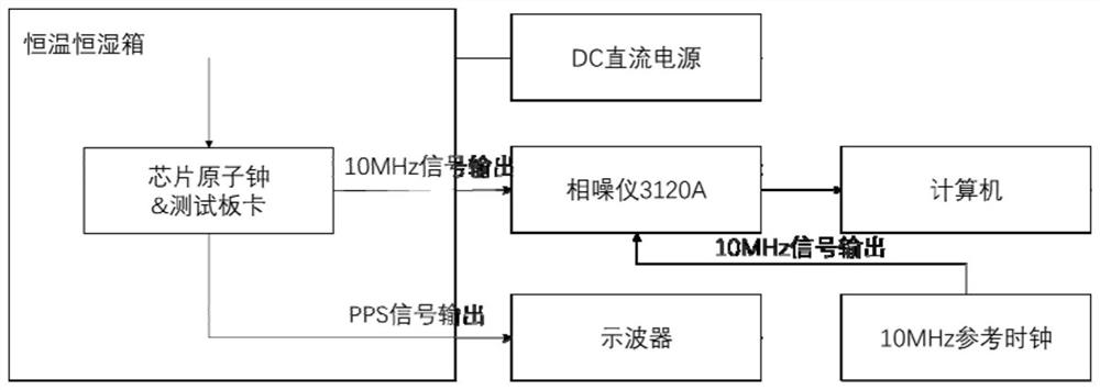
[0038] This embodiment discloses an accelerated aging reliability test device for a chip atomic clock. The device includes: a test board, a temperature and humidity box, a reference clock, an oscilloscope, a DC power supply, a phase noise tester, and a computer. The test board The card is placed in a temperature and humidity box, and a plurality of chip atomic clocks are installed on a test board card. The test board card is provided with a chip atomic clock socket 1, a voltage conversion module, a signal output module and a power interface 6. The DC power supply The power supply interface 6 supplies power to the test board, the voltage conversion module supplies power to the chip atomic clock, and the signal output module is connected to an oscilloscope, a phase noise tester and computer equipment to evaluate the time and frequency signal quality of the chip atomic clock.

[0039] The power interface 6 is connected to the DC power supply, and a plurality of chip atomic clocks ...

Embodiment 2

[0044] This embodiment discloses an accelerated aging reliability test method for a chip atomic clock, and the method is as follows:

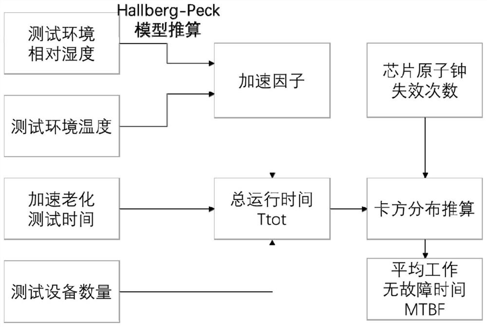
[0045] Place a number of chip-level atomic clocks on the test board; place the board of the chip atomic clock in a temperature and humidity box, adjust the temperature inside the box to 40°C and 85% relative humidity, and connect the test board to the power supply outside the box and turn it on. Continue to work under the conditions, the oscilloscope tests the quality of the second pulse signal to detect the frequency of faults, the phase noise tester measures the measurement signal and sends it to the computer, calculates the acceleration factor through the acceleration model, and finally obtains the mean time between failures MTBF.


PUM


Abstract

The invention discloses an accelerated aging reliability test device and method for a chip atomic clock. The device comprises: a test board, a temperature and humidity box, a reference clock, an oscilloscope, a DC power supply, a phase noise tester and a computer. The board is placed in a temperature and humidity box, and a plurality of chip atomic clocks are installed on the test board. The test board is provided with a chip atomic clock socket, a voltage conversion module, a signal output module and a power interface. The power interface supplies power to the test board, the voltage conversion module supplies power to the chip atomic clock, the signal output module performs dual signal output, and the signal output module is connected to an oscilloscope, a phase noise tester and computer equipment to the chip atomic clock time and frequency signals quality is assessed. The invention solves the problems of low reliability test efficiency and high cost of the existing chip atomic clock.

Description

technical field [0001] The invention relates to the technical field of reliability testing of atomic clocks, in particular to an accelerated aging reliability testing device and method for chip atomic clocks. Background technique [0002] MTBF (Mean Time Between Failure), the mean time between failures, is a measure of the reliability of a product. The measurement method is: the ratio of the total number of life units of the product to the total number of failures under the specified conditions and within the specified time. The MTBF value is an important parameter to be considered when designing a product. Reliability engineers or designers often use various methods and standards to estimate the MTBF value of a product. [0003] The CPT atomic clock is a new type of atomic clock realized by using the coherent layout trapping principle of atoms. Since a microwave resonator is no longer required, it can be truly miniaturized. The time of the crystal oscillator is "milliseco...

Claims


Application Information

Patent Timeline
Patent Type & Authority Patents(China)
IPC IPC(8): G04D7/00
CPCG04D7/002G04D7/00
Inventor 孟红玲董万霖
Owner 中科启迪光电子科技(广州)有限公司
Learn More