Pipe laser cutting machine

A laser cutting machine and laser cutting technology, applied in the direction of laser welding equipment, tubular objects, manufacturing tools, etc., can solve the problems of reducing the feeding rate of pipes, the positioning accuracy of pipes, and the quality of pipe processing, so as to prevent deviation and improve The effect of processing quality

Inactive Publication Date: 2022-05-13
山东欧锐激光科技有限公司
View PDF8 Cites 1 Cited by
  • Summary
  • Abstract
  • Description
  • Claims
  • Application Information

AI Technical Summary

Problems solved by technology

Most of the cutting machines in the prior art use hydraulic chucks to clamp the pipe and manually feed the material, which reduces

Method used


Image

  • Pipe laser cutting machine
  • Pipe laser cutting machine
  • Pipe laser cutting machine

Examples


Embodiment Construction

[0018] In order to make the purpose, features and advantages of the present invention more obvious and understandable, the technical solutions in the present invention will be clearly and completely described below in conjunction with the accompanying drawings in this specific embodiment. Obviously, the implementation described below Examples are only some embodiments of the present invention, but not all embodiments. Based on the embodiments in this patent, all other embodiments obtained by persons of ordinary skill in the art without creative efforts fall within the protection scope of this patent.

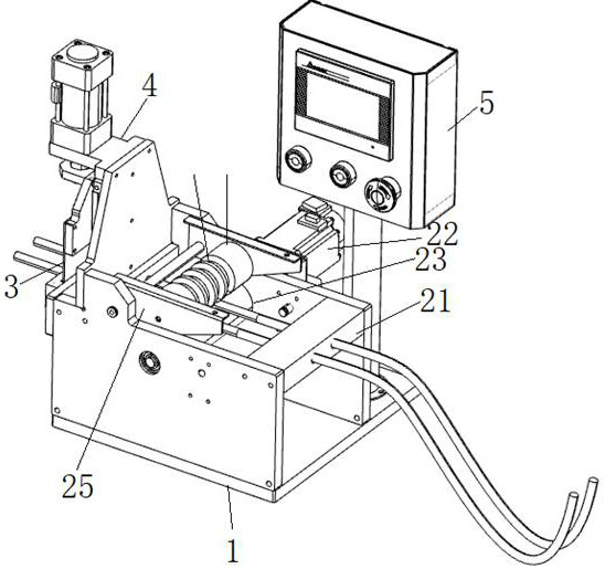
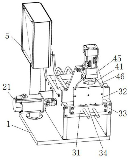
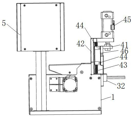
[0019] refer to Figure 1-3 As shown, the present invention provides a pipe laser cutting machine, comprising a workbench 1, a feed conveying mechanism 2, a guide mechanism 3, a laser cutting device 4 and a control mechanism 5; the feed conveying mechanism 2 is arranged on the workbench 1, the guide mechanism 3 is arranged on one side of the feeding conveying mechanism 2 and is...


PUM


Abstract

The invention discloses a pipe laser cutting machine, which relates to the field of laser cutting devices, and comprises a workbench, a feeding conveying mechanism, a guide mechanism, a laser cutting device and a control mechanism, the feeding conveying mechanism is arranged on the upper portion of the workbench, the guiding mechanism is arranged on one side of the feeding conveying mechanism and used for clamping a pipe to be cut, and the laser cutting device is arranged on the upper portion of the guiding mechanism and used for cutting the pipe. The control mechanism is arranged on one side of the workbench and electrically connected with the feeding conveying mechanism and the laser cutting device, the pipe feeding rate is guaranteed, pipe positioning is facilitated, pipe deviation is prevented, the pipe machining quality is improved, and pipe machining and cutting can be achieved through the laser cutting device.

Description

technical field [0001] The invention relates to the field of laser cutting devices, in particular to a tube laser cutting machine. Background technique [0002] The laser cutting machine focuses the laser light emitted from the laser device into a high power density laser beam through the optical path system. The laser beam irradiates the surface of the workpiece to make the workpiece reach the melting point or boiling point, and at the same time, the high-pressure gas coaxial with the beam blows away the molten or vaporized metal. With the movement of the relative position of the beam and the workpiece, the material will eventually form a slit, so as to achieve the purpose of cutting. Since the mechanical part of the laser cutter head has no contact with the workpiece, it will not scratch the surface of the workpiece during work, so laser cutting machines are more and more widely used. Most of the cutting machines in the prior art use hydraulic chucks to clamp the pipe an...

Claims


Application Information

Patent Timeline
IPC IPC(8): B23K26/38B23K26/70
CPCB23K26/38B23K26/702B23K2101/06
Inventor 周昌卫
Owner 山东欧锐激光科技有限公司
Why Eureka
Try Eureka