
Water-permeable box body for constructing flow separation embankment and flow separation embankment structure

A non-permeable, box-like technology, applied in dikes, buildings, dams, etc., can solve problems such as difficulty in meeting the requirements of lateral flow velocity and return flow velocity, deterioration of navigation conditions of ship locks, difficulty in adjusting the entrance area, etc., to shorten the construction period, The effect of reducing the amount of excavation, good anti-tilting and anti-shock ability

Pending Publication Date: 2022-05-13
CHONGQING JIAOTONG UNIVERSITY
View PDF0 Cites 0 Cited by
  • Summary
  • Abstract
  • Description
  • Claims
  • Application Information

AI Technical Summary

Problems solved by technology

In mountainous rivers, when there is a drop between the entrance area and the left and right banks, or when there is a bend in the river section, the flow velocity and direction in the main river channel are quite different from the flow velocity and direction in the entrance area. Difficulty adjusting to chaotic flow patterns in the entrance area
When the traditional dike layout is adopted, when there is a large gradient between the flow velocity of the main river and the entrance area, the water with a large flow rate enters the approach channel and the entrance area through the perforated hole and then floats further, resulting in the deterioration of the flow state in the entrance area , it is difficult to meet the requirements of lateral flow velocity and return flow velocity in navigation regulations
In addition, the high-velocity water stream will also carry sediment and deposit it in the approach channel and the entrance area, which will deteriorate the navigation conditions of the ship lock.
In the layout of the traditional ship lock gate area, the barrier embankment will be further extended to the river section with a small flow velocity gradient. Such measures will increase the amount of construction work, especially the excavation of cofferdams and foundation pits during the dry season, which will prolong the construction period and increase the invest

Method used


Image

  • Water-permeable box body for constructing flow separation embankment and flow separation embankment structure
  • Water-permeable box body for constructing flow separation embankment and flow separation embankment structure
  • Water-permeable box body for constructing flow separation embankment and flow separation embankment structure

Examples


Embodiment 1

[0048] The engineering overview of embodiment 1 and comparative example 1,2 is as follows:

[0049] The maximum navigable discharge Q=5500 m of a navigation and power junction on a mountainous river in southwest China 3 / s, most of the ore ships pass through the navigation and power hub, and the flood level and water depth of 8 m are often encountered at the exit of the entrance area. A diversion wall with a length of 370 m is built in the downstream approach channel. Under the condition of no diversion dike behind the diversion wall, the lateral flow velocity and return flow velocity in the gate area do not meet the requirements of the "Overall Design Code for Ship Locks", resulting in the ship's maneuverability and stability. Sex is poor.

[0050] For the above-mentioned projects, different dikes were set up in the downstream approach channel of the navigation and power hub according to Example 1 and Comparative Examples 1 and 2, and experimental research on flow patterns a...

Embodiment 2

[0061] The engineering overview of embodiment 2 and comparative example 3,4 is as follows:

[0062] The maximum navigable discharge Q=7500 m of a navigation and power junction on a mountainous river in southwest China 3 / s, most of the navigation and power hubs are bulk cargo ships, and the flood level and water depth of 9 m are often encountered at the exit of the entrance area. A 120-meter-long diversion wall is built in the downstream approach channel. Under the condition that there is no diversion dike behind the diversion wall, the lateral flow velocity and return flow velocity in the entrance area do not meet the requirements of the "General Design Code for Ship Locks", resulting in ship maneuverability and stability. Sex is poor.

[0063] For the above-mentioned projects, different dikes were set up in the approach channel downstream of the navigation and power hub according to Example 2 and Comparative Examples 3 and 4, and experimental research on flow patterns and s...


PUM


Abstract

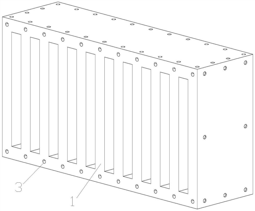
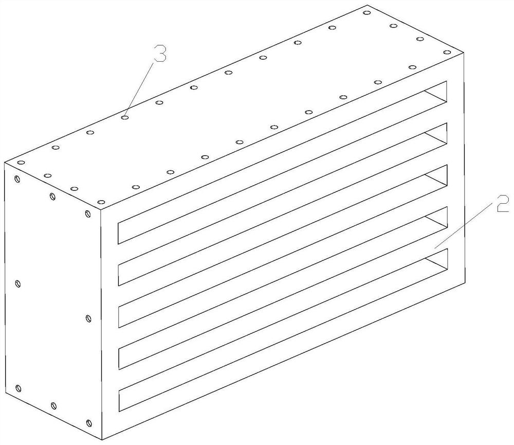
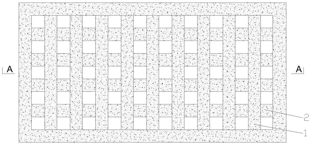
The invention discloses a permeable box body for constructing a flow separation embankment and a flow separation embankment structure, the front and back surfaces of the permeable box body are open, a vertical grid layer and a transverse grid layer are vertically arranged in the box body, the vertical grid layer is composed of a plurality of vertical grids, the transverse grid layer is composed of a plurality of transverse grids, and the transverse grid layer is composed of a plurality of transverse grids. The vertical grid layers and the transverse grid layers are arranged at intervals, and the plane where the vertical grid layers and the transverse grid layers are located is parallel to the front face and the rear face of the box body. The invention further provides a flow separation dyke structure, the flow separation dyke is composed of a permeable unit located on the lower layer and a non-permeable unit located on the upper layer in the length direction of the flow separation dyke, and the permeable unit is formed by alternately and fixedly connecting a plurality of non-permeable box bodies and a plurality of permeable box bodies in the length direction of the flow separation dyke. The non-permeable unit is formed by fixedly connecting a plurality of non-permeable box bodies side by side in the length direction of the flow separation embankment. The flow separation embankment is flexible, has anti-tilting and anti-impact capacities, can ensure that water flow in a main river channel enters an approach channel to form a stable flow state, and reduces deposition of silt in the approach channel.

Description

technical field [0001] The invention belongs to the technical field of water conservancy and water transportation, and in particular relates to a permeable box body and a dike structure for constructing a dike. Background technique [0002] After the construction of water conservancy or shipping hub projects on natural rivers, in order to meet the needs of navigation, it is often necessary to set up navigation structures such as ship locks. The area where the approach channel of the ship lock is connected with the river is called the gate area, which is the transition area between the still water in the approach channel of the ship lock and the moving water outside the approach channel of the hub section. Large, horizontal flow velocity, longitudinal flow velocity and return flow velocity do not meet the standards of navigable water flow and the depth of the ship's navigation is insufficient. When the ship sails through the waters, it will drift or reverse due to the advers...

Claims


Application Information

Patent Timeline
Patent Type & Authority Applications(China)
IPC IPC(8): E02B3/10E02C1/00
CPCE02B3/10E02C1/00
Inventor 何小泷周昔东袁浩胡瑞昌谢春航
Owner CHONGQING JIAOTONG UNIVERSITY
Learn More