
Simulated tripping equipment applicable to multi-size tubular columns

A multi-size, string technology, applied in the testing of mechanical equipment, mechanical parts, machine/structural parts, etc., to reduce the difficulty of operation and improve work efficiency

Active Publication Date: 2022-05-13
山东普瑞思德石油技术有限公司
View PDF6 Cites 0 Cited by
  • Summary
  • Abstract
  • Description
  • Claims
  • Application Information

AI Technical Summary

Problems solved by technology

The first thing that bears the brunt is the immature lifting equipment for simulating horizontal wells

Method used


Image

  • Simulated tripping equipment applicable to multi-size tubular columns
  • Simulated tripping equipment applicable to multi-size tubular columns
  • Simulated tripping equipment applicable to multi-size tubular columns

Examples


Embodiment 1

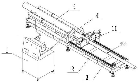
[0029] refer to figure 1 As shown, a simulated lifting equipment applicable to multi-size pipe strings includes a transmission device and a control device 1 , and the transmission device includes a transmission base, a clamping mechanism and an operating cylinder 18 .

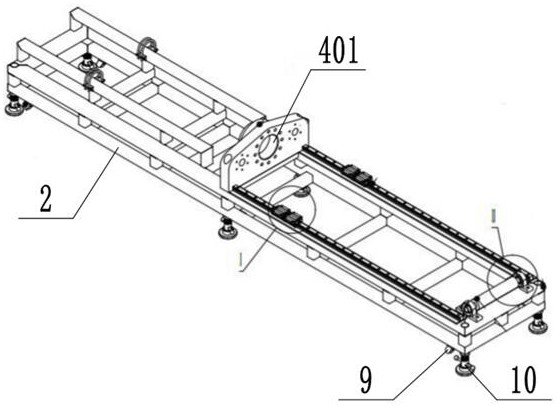
[0030] refer to Figure 2-4 As shown, the transmission base includes a transmission frame 2, a long guide rail 3, auxiliary rollers, a fixed plate 4 and a simulated column 5, the fixed plate 4 is vertically fixed and installed in the middle of the transmission frame 2, and the simulated column 5 is fixedly installed on the side of the fixed plate 4. On the rear end surface, and the fixed plate 4 is provided with a through hole 401 communicating with the simulated pipe string 5; the inner diameter of the through hole 401 is greater than or equal to the inner diameter of the simulated pipe string 5, and a plurality of long guide rails 3 are fixed and installed side by side on the front side of the fixed plate 4 ...

Embodiment 2

[0043] As a preferred embodiment of the present invention, this embodiment adds a moving assembly and a fixed assembly at the bottom of the transmission rack 2 on the basis of Embodiment 1, specifically:

[0044] refer to figure 2 As shown, in this embodiment, a number of pulleys 9 and an adjustment base 10 are evenly distributed on the bottom of the transmission frame 2, and the height of the adjustment base 10 is adjustable.

[0045] There is a pulley 9 on the transmission base, and the transmission base is placed in the test area through the pulley 9; the adjustment base 10 is raised to fix the transmission base to the corresponding test area.

Embodiment 3

[0047] As a preferred embodiment of the present invention, this embodiment optimizes the long guide rail 3 on the basis of Embodiment 2, specifically:

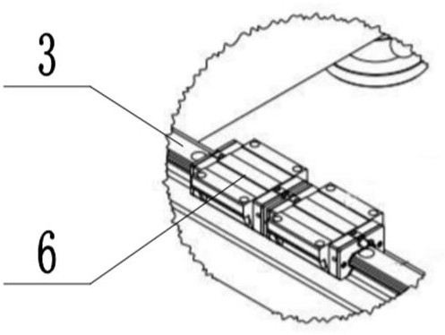
[0048] In this embodiment, two long guide rails 3 are provided, and two slide rail seats 6 are slidably installed on each long guide rail 3; the slide rail seats 6 of this embodiment are ball-type linear slide rail seats 6, and It is beneficial to improve the stability of the operation of the clamping mechanism.


PUM


Abstract

The invention discloses simulation tripping equipment applicable to tubular columns of multiple sizes, and relates to the technical field of simulation test well tripping operation equipment, the simulation tripping equipment comprises a conveying device and a control device, the conveying device comprises a conveying base body, a clamping mechanism and an action oil cylinder, and the conveying base body comprises a conveying frame, a long guide rail, an auxiliary roller, a fixing plate and a simulation tubular column; the clamping mechanism comprises a movable plate, a positioning clamping seat and a small oil cylinder, the movable plate is installed on the sliding rail seat, a plurality of action oil cylinders are fixedly installed on the conveying frame on the rear side of the fixed plate side by side, the front end of a cylinder body is fixedly installed on the fixed plate, a pressure sensor is arranged between the front end of the cylinder body and the fixed plate, and a hydraulic rod of the cylinder body penetrates through the fixed plate and is fixedly connected with the movable plate; the small oil cylinder, the distance sensor, the action oil cylinder and the pressure sensor are all electrically connected with the control device; the device can be applied to simulation of lifting of a horizontal well test tubular column, can also be used for simulation of lifting of a straight inclined shaft test tubular column, and is suitable for tubular columns of various sizes and specifications.

Description

technical field [0001] The invention relates to the technical field of operating equipment for lifting and lowering pipe strings in simulated test wells, in particular to a simulated lifting and lowering equipment applicable to pipe strings of multiple sizes. Background technique [0002] In the current technical field of oil drilling and completion, as the length of oil and gas field wells increases, the working conditions become more and more complex. come higher. In order to ensure the stability and reliability of the process string, it is necessary to carry out multiple simulation tests on the corresponding process string. During the simulation test, small-scale hydraulic equipment or even manpower are often used to lift and lower the process string, which is laborious and laborious. Once problems such as sand stuck in the process string occur, it is difficult to lift the process string again, and the process string can only be damaged. , before it can be removed, whic...

Claims


Application Information

Patent Timeline
Patent Type & Authority Applications(China)
IPC IPC(8): G01M13/00F15B21/08
CPCG01M13/00F15B21/08
Inventor 邢秀贵耿瑞琪吴海燕徐晓跃王玉婷刘智仁孙锐杰王鹏
Owner 山东普瑞思德石油技术有限公司
Learn More