Backlight module and display device

A backlight module and backplane technology, which is applied in identification devices, light guides, optics, etc., can solve the problems of light guide plate and other film deformation, high heat generation of lamp beads, and potential heat dissipation hazards, etc., to improve light intensity, light and thin The effect of the design

Pending Publication Date: 2022-05-13
CHONGQING HKC OPTOELECTRONICS TECH CO LTD +1
View PDF0 Cites 0 Cited by
  • Summary
  • Abstract
  • Description
  • Claims
  • Application Information

AI Technical Summary

Problems solved by technology

[0003] In the related art, the direct-type backlight module needs to lay strip light sources on the entire surface of the backplane. Although it can ensure higher light brightness, it is easy to increase the overall thickness of the backlight module. The combination of the display panel and the backlight module is formed. The large size of the display device does not conform to the mainstream design concept of light and thin display devices in the market, and it is gradually not favored by users
Because the LEDs of the side-entry backlight module are set on the side frame of the back panel, limited by the limited space on the side frame of the back panel, the theoretical number of LEDs that can be installed in the side-entry backlight module is small To increase the light intensity of the backlight module, it is necessary to increase the luminous power of a single lamp bead. On the one hand, it will easily lead to an increase in the power consumption of the backlight module. Films such as light guide plates in the group are prone to deformation due to heat

Method used


Image

  • Backlight module and display device
  • Backlight module and display device
  • Backlight module and display device

Examples


no. 1 example

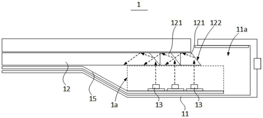
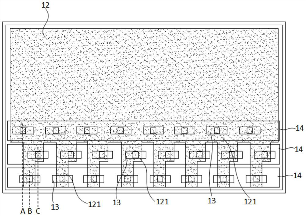
[0037] combine figure 1 and figure 2 As shown, the above-mentioned backlight module 1 includes a back plate 11 and a light guide plate 12, the back plate 11 is provided with a cavity 11a, and the light guide plate 12 is arranged in the cavity 11a; In the accommodating space 1a, the light guide plate 12 is provided with a plurality of reflective convex portions 121 extending toward the accommodating space 1a; the backlight module 1 further includes a plurality of point light sources 13 disposed in the accommodating space 1a, each reflective convex portion 121 It is used to reflect the light emitted by at least one point light source 13 into the light guide plate 12 for uniform diffusion.

[0038] In this embodiment, one end of the back plate 11 may be provided with a groove body, the groove body is located at one end of the bottom wall of the accommodating groove 11a, and the groove wall of the groove body and the light guide plate 12 are enclosed to form the above-mentioned ...

no. 2 example

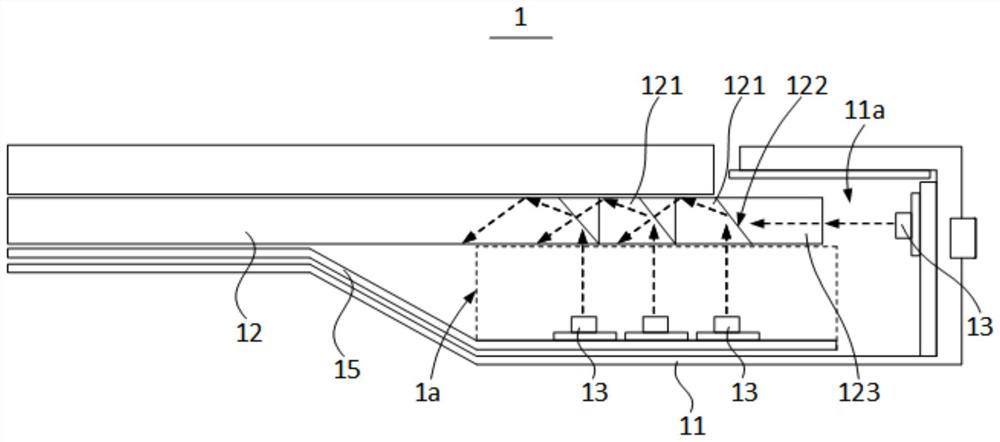
[0042] like image 3 As shown, the difference between this embodiment and the first embodiment is that in this embodiment, a plurality of point light sources 13 are also provided on the side walls of the above-mentioned accommodating groove 11a; A plurality of light guide protrusions 123 extending from the side walls are provided, and each point light source 13 disposed on the side wall of the accommodating groove 11a is correspondingly provided with a light guide protrusion 123 .

[0043] In this embodiment, the point light sources 13 are also arranged on the side walls of the container groove 11a, so that the space between the light guide plate 12 and the side wall of the back plate 11 is fully utilized, and the number of point light sources 13 provided in the backlight module 1 is increased, and the The light emitted by the point light source 13 located on the side wall of the container 11a is received and guided by the light guide protrusions 123 to enter the light guide p...

no. 3 example

[0045] like Figure 4 As shown, the difference between this embodiment and the first embodiment is that the above-mentioned accommodating spaces 1a are formed between the opposite ends of the back plate 11 and the light guide plate 12; the opposite ends of the light guide plate 12 are provided with multiple The light-reflecting protrusions 121 each extend toward an accommodating space 1a, and each accommodating space 1a is provided with a plurality of point light sources 13 .

[0046] In the present embodiment, an accommodating space 1a is provided in each of the opposite ends of the backlight module 1 along the length direction of the light guide plate 12, and each accommodating space 1a is in the same way as the first embodiment. A plurality of point light sources 13 and a plurality of light-reflecting protrusions 121 are provided, and the light emitted by the point light sources 13 in the two accommodating spaces 1a is respectively reflected by the light-reflecting protrusi...


PUM


Abstract

The invention relates to the technical field of display, and discloses a backlight module and a display device.The backlight module comprises a back plate and a light guide plate, the back plate is provided with a containing groove, and the light guide plate is arranged in the containing groove; a containing space is formed between at least one end of the bottom wall of the containing groove and the light guide plate, and the light guide plate is provided with a plurality of light reflecting convex parts extending towards the interior of the containing space; the backlight module further comprises a plurality of point light sources arranged in the containing space, and each light reflecting convex part is used for reflecting light emitted by at least one point light source into the light guide plate to be evenly diffused. The backlight module and the display device provided by the invention have higher light emitting brightness.

Description

technical field [0001] The invention relates to the field of display technology, in particular to a backlight module and a display device. Background technique [0002] In order to improve the contrast ratio of the display screen of the display panel, the backlight module that provides the backlight for the display panel needs to have higher light output brightness. [0003] In the related art, the direct type backlight module needs to lay a strip light source on the entire surface of the back panel. Although it can ensure higher light output brightness, it easily leads to an increase in the overall thickness of the backlight module. The volume of the display device is relatively large, which does not conform to the light and thin design concept of the display device in the mainstream of the market, and is gradually not favored by users. Because the lamp beads are arranged on the side frame of the back panel, the edge-type backlight module is limited by the very limited spa...

Claims


Application Information

Patent Timeline
Patent Type & Authority Applications(China)
IPC IPC(8): G02B6/00G09F9/00
CPCG02B6/0088G02B6/009G02B6/0031G02B6/0068G02B6/0028G02B6/0055G09F9/00
Inventor 万业袁海江
Owner CHONGQING HKC OPTOELECTRONICS TECH CO LTD
Why Eureka
Try Eureka