BMS constant-current pre-charging circuit

A pre-charging circuit and pre-charging technology, applied in circuits, circuit devices, battery circuit devices, etc., can solve the problems of inability to diagnose whether the main relay and the pre-charging relay are adhered to failure, components burned out, and low reliability.

Pending Publication Date: 2022-05-13
SUNWODA ELECTRIC VEHICLE BATTERY CO LTD
View PDF0 Cites 0 Cited by
  • Summary
  • Abstract
  • Description
  • Claims
  • Application Information

AI Technical Summary

Problems solved by technology

D) Repeated pre-charging causes repeated impact on the current-limiting resistor, resulting in short life and low reliability of the current-limiting resistor
E) It is impossible to diagnose whether the adhesion of the main relay and the pre-charge

Method used


Image

  • BMS constant-current pre-charging circuit

Examples


Embodiment Construction

[0017] The following will clearly and completely describe the technical solutions in the embodiments of the present invention with reference to the accompanying drawings in the embodiments of the present invention. Obviously, the described embodiments are only some, not all, embodiments of the present invention. Based on the embodiments of the present invention, all other embodiments obtained by persons of ordinary skill in the art without making creative efforts belong to the protection scope of the present invention.

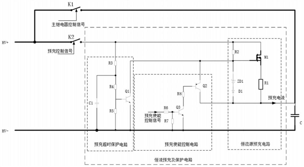
[0018] Please refer to the attached figure 1 , which is a circuit structure diagram of a BMS constant current precharging circuit according to an embodiment of the present invention. As an example, a BMS constant current precharging circuit in this embodiment includes a constant current source precharging circuit, one end of the constant current source precharging circuit is connected to an external capacitor C, and the constant current source precharging circ...


PUM


Abstract

The invention relates to the technical field of battery management systems, in particular to a BMS constant-current pre-charging circuit which comprises a constant-current source pre-charging circuit, one end of the constant-current source pre-charging circuit is connected with an external capacitor C, and the other end of the constant-current source pre-charging circuit is connected with an external pre-charging relay K2. The capacitor C is also connected with an external battery pack through an external main relay K1; the constant current source pre-charging circuit comprises an MOS tube M1, a bias resistor R2, a Zener diode ZD1 and a resistor R1. According to the BMS constant-current pre-charging circuit, the constant-current source pre-charging circuit is used for carrying out constant-current pre-charging on the capacitor C at the load end, no large instantaneous impact current exists in the pre-charging process, the type selection specifications of a pre-charging relay and a current-limiting resistor are effectively reduced, the size of the relay is further reduced, the cost is reduced, and the circuit reliability is improved.

Description


Claims


Application Information

Patent Timeline
Owner SUNWODA ELECTRIC VEHICLE BATTERY CO LTD
Why Eureka
Try Eureka