Beneficiation thickener with defoaming device

A technology of defoaming device and thickener, which is applied to the feeding/discharging device of the sedimentation tank, foam dispersion/prevention, separation method, etc., can solve the problems of reducing the efficiency of the thickener and slowing down the particle settling speed.

Active Publication Date: 2022-05-17
ANHUI KAIFA MINING IND
View PDF14 Cites 0 Cited by
  • Summary
  • Abstract
  • Description
  • Claims
  • Application Information

AI Technical Summary

Problems solved by technology

[0002] The thickener is a kind of thickening and clarifying equipment that works continuously. It is mainly used for the dehydration of fine and tailings slurry in wet beneficiation. It uses the gravity sedimentation of particles as the working principle to realize material separation. There will be a lot of foam on the surface, because the solid particles will attach to the air bubbles, which will slow down the settling speed of the particles and greatly reduce the efficiency of the thickener. Therefore, it is necessary to install a defoaming device on the top of the thickener to remove the air bubbles.
[0003] Most of the existing thickeners use the spray method to eliminate the bubbles on the liquid surface. During the spraying process, the water droplets will break the larger bubbles, but because the small water droplets hit the liquid surface under the action of gravity, many small bubbles will be formed. This makes the bubbles still exist in the local area above the liquid surface. At the same time, there are a lot of bubbles at the edge of the existing thickener during use.

Method used


Image

  • Beneficiation thickener with defoaming device
  • Beneficiation thickener with defoaming device
  • Beneficiation thickener with defoaming device

Examples


Embodiment 1

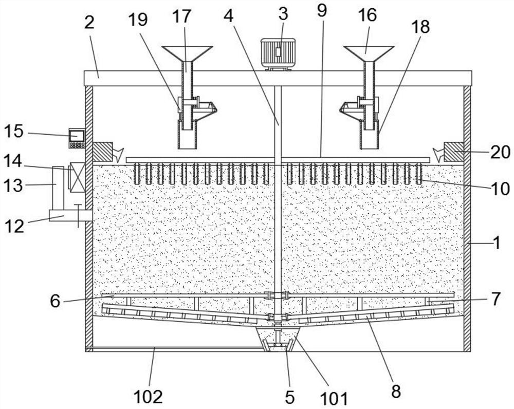
[0031] Such as Figure 1-3 As shown, a thickener for beneficiation with a defoaming device, including

[0032] Thickener body 1, the bottom of the thickener body 1 is provided with a discharge hopper 101, and one side of the discharge hopper 101 is provided with a discharge trough 102, and the top of the thickener body 1 is fixedly installed with a beam 2, and the top of the beam 2 A motor 3 is fixedly installed on the side, the output shaft of the motor 3 runs through the beam 2 and a rotating shaft 4 is fixedly installed, the bottom end of the rotating shaft 4 extends into the discharge hopper 101 and a stirring blade 5 is fixedly installed,

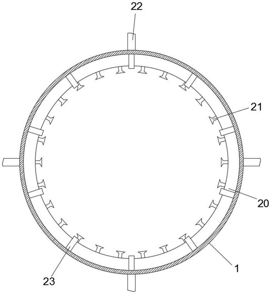
[0033] Bubble-gathering assembly, the bubble-gathering assembly includes water outlet pipe 20, nozzle 21 and water inlet pipe 22, and the top of the inner wall of the thickener body 1 is fixed with a ring-shaped water outlet pipe 20, and the water outlet pipe 20 is far away from the thickener body 1- Several groups of nozzles 21 are a...

Embodiment 2

[0043] On the basis of Example 1, such as Figure 4-6 As shown, the similarities will not be repeated, and the difference is that a sludge bucket 16 is provided on the top of the beam 2, and a feed pipe 17 is fixedly installed at the bottom of the sludge bucket 16, and the bottom end of the feed pipe 17 is Through the beam 2 and fixedly connected with it, the bottom end of the feed pipe 17 is sleeved with a telescopic pipe 18, and the side wall of the feed pipe 17 is fixedly equipped with an electric push rod 19, and the telescopic end of the electric push rod 19 is connected to the Telescopic tube 18 tops are fixedly connected.

[0044] A guide plate 25 is fixedly installed on the side of the feed pipe 17 away from the electric push rod 19, and a first guide pulley 26 is installed on the end of the guide plate 25 away from the side wall of the feed pipe 17, and a guide pulley 26 is installed on the upper side of the guide plate 25. The second guide pulley 27, the inside of t...


PUM


Abstract

The invention relates to the technical field of defoaming of thickeners, and discloses a mineral separation thickener with a defoaming device, the mineral separation thickener comprises a thickener body, the top of the thickener body is fixedly provided with a cross beam, the upper side of the cross beam is fixedly provided with a motor, and an output shaft of the motor penetrates through the cross beam and is fixedly provided with a rotating shaft; the bottom end of the rotating shaft extends into the discharging hopper and is fixedly provided with stirring blades and a bubble gathering assembly, the bubble gathering assembly comprises a water outlet pipe, an annular water outlet pipe is fixedly installed at the top of the inner wall of the thickener body, and a spray head is arranged on the side, away from the thickener body, of the water outlet pipe; and the defoaming assembly comprises a transverse rod, defoaming rods and defoaming teeth, the transverse rod is fixedly installed on the outer side of the rotating shaft and located on the upper side of the liquid level, the multiple sets of defoaming rods are fixedly installed on the bottom side of the transverse rod, and the defoaming teeth are arranged on the defoaming rods. Bubbles on the upper portion of the liquid level can be comprehensively eliminated, and the problem that bubbles still exist in a local area due to traditional spraying defoaming is solved.

Description

Technical field: [0001] The invention relates to the technical field of thickener defoaming, in particular to a thickener for ore dressing with a defoaming device. Background technique: [0002] The thickener is a kind of thickening and clarifying equipment that works continuously. It is mainly used for the dehydration of fine and tailings slurry in wet beneficiation. It uses the gravity sedimentation of particles as the working principle to realize material separation. There is a lot of foam on the surface, because solid particles will attach to the air bubbles, which will slow down the sedimentation speed of the particles and greatly reduce the efficiency of the thickener. Therefore, it is necessary to install a defoaming device on the top of the thickener to remove the air bubbles. [0003] Most of the existing thickeners use the spray method to eliminate the bubbles on the liquid surface. During the spraying process, the water droplets will break the larger bubbles, but ...

Claims


Application Information

Patent Timeline
Patent Type & Authority Applications(China)
IPC IPC(8): B01D21/24B01D21/34B01D19/00B01D19/02
CPCB01D21/2405B01D21/245B01D21/34B01D19/0042B01D19/02Y02P10/20
Inventor 王涛武利朔龚豪李超黄叶峰袁勇杰王博文张贵祥
Owner ANHUI KAIFA MINING IND
Why Eureka
Try Eureka