Rust removal system and rust removal method for drainage pipe for water conservancy irrigation
A drainage pipe and water conservancy technology, which is applied to the parts of grinding machine tools, abrasive surface adjustment devices, manufacturing tools, etc., can solve the problem that the effective contact between the wire brush and the inner diameter of the drainage pipe cannot be guaranteed, rust removal marks are easily left, and the processing environment is harsh and other problems to achieve the effect of ensuring cleanliness and health, improving service life and simple operation
- Summary
- Abstract
- Description
- Claims
- Application Information
AI Technical Summary
Problems solved by technology
Method used
Image
Examples
Embodiment 1
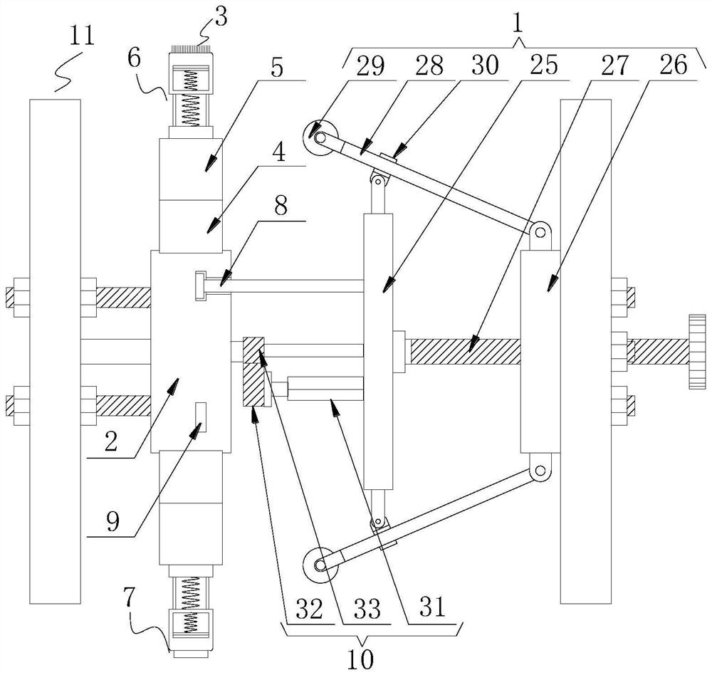
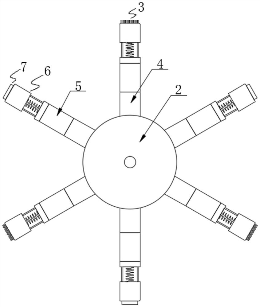
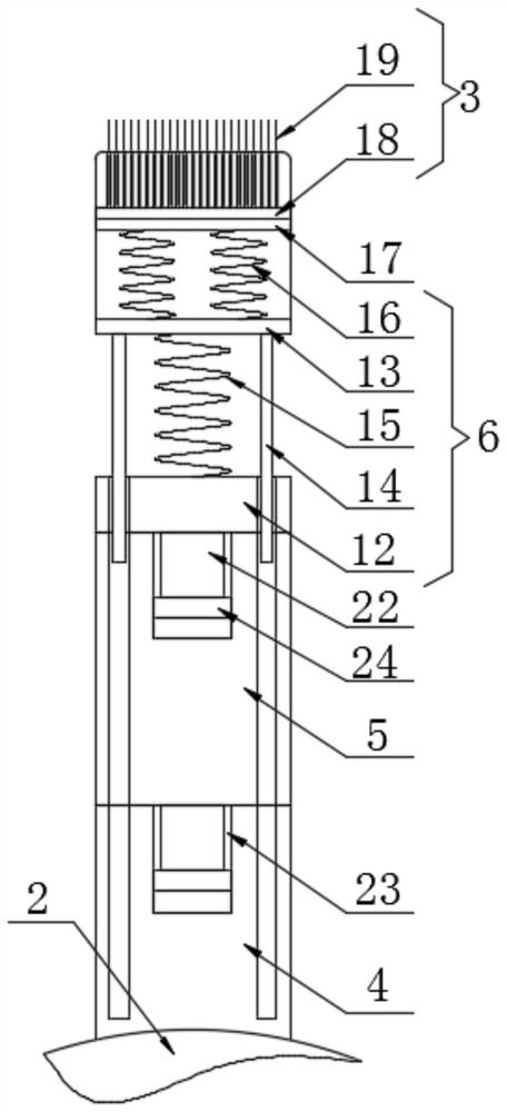
[0053] A rust removal system for drainage pipes for water conservancy and irrigation, comprising a guide frame 1, a support ring 2 and at least three rust removal brushes 3 arranged on the support ring 2, the outer circumference of the support ring 2 is evenly spaced and fixedly connected with at least six Fixed cylinder 4, the end of the fixed cylinder 4 far away from the support ring 2 is clamped and fixed with a length adjustment member 5, and the end of the length adjustment member 5 far away from the fixed cylinder 4 is clamped and fixed with an elastic extrusion cylinder 6, and three derusting brushes 3 are placed Inside the elastic extruding cylinder 6, the insides of the other three elastic extruding cylinders 6 are provided with smoothing heads 7, the left side of the guide frame 1 is fixedly connected with at least three limit rods 8, and the right side of the support ring 2 is provided with a The limit groove 9 matched with the limit rod 8, the drive assembly 10 is f...
Embodiment 2
[0055] As an improvement of the previous embodiment, this embodiment includes a guide frame 1, a support ring 2 and at least three rust removal brushes 3 arranged on the support ring 2, as attached figure 1 As shown, the guide frame 1 includes a limiting plate 25 and a moving plate 26, the right side of the moving plate 26 runs through and is threadedly connected with a threaded rod 27, the left end of the threaded rod 27 is rotationally connected with the right side of the limiting plate 25 through a bearing, and moves The top, the bottom and the front and rear sides of plate 26 are all rotated and connected with support plate 28 by turning block, and support plate 28 is connected with moving roller 29 in rotation away from one end of moving plate 26, as attached Figure 8 As shown, the top, bottom and front and rear sides of the limiting plate 25 are rotatably connected with the I-shaped block 30 through the rotating block, and the surface of the support plate 28 is provided ...
PUM
 Abstract
Description
Claims
Application Information
 - R&D
- Intellectual Property
- Life Sciences
- Materials
- Tech Scout
- Unparalleled Data Quality
- Higher Quality Content
- 60% Fewer Hallucinations
Browse by: Latest US Patents, China's latest patents, Technical Efficacy Thesaurus, Application Domain, Technology Topic, Popular Technical Reports.
© 2025 PatSnap. All rights reserved.Legal|Privacy policy|Modern Slavery Act Transparency Statement|Sitemap|About US| Contact US: help@patsnap.com


