Gas leakage monitoring alarm device for coal mine operation
An alarm device and gas technology, applied in mining devices, mining equipment, earth-moving drilling, etc., can solve the problems of gas leakage, insufficient detection speed of gas alarm lights, inability to assist effective coal mine work, etc., and achieve the effect of preventing insufficient sensitivity
- Summary
- Abstract
- Description
- Claims
- Application Information
AI Technical Summary
Problems solved by technology
Method used
Image

Examples
Embodiment 1
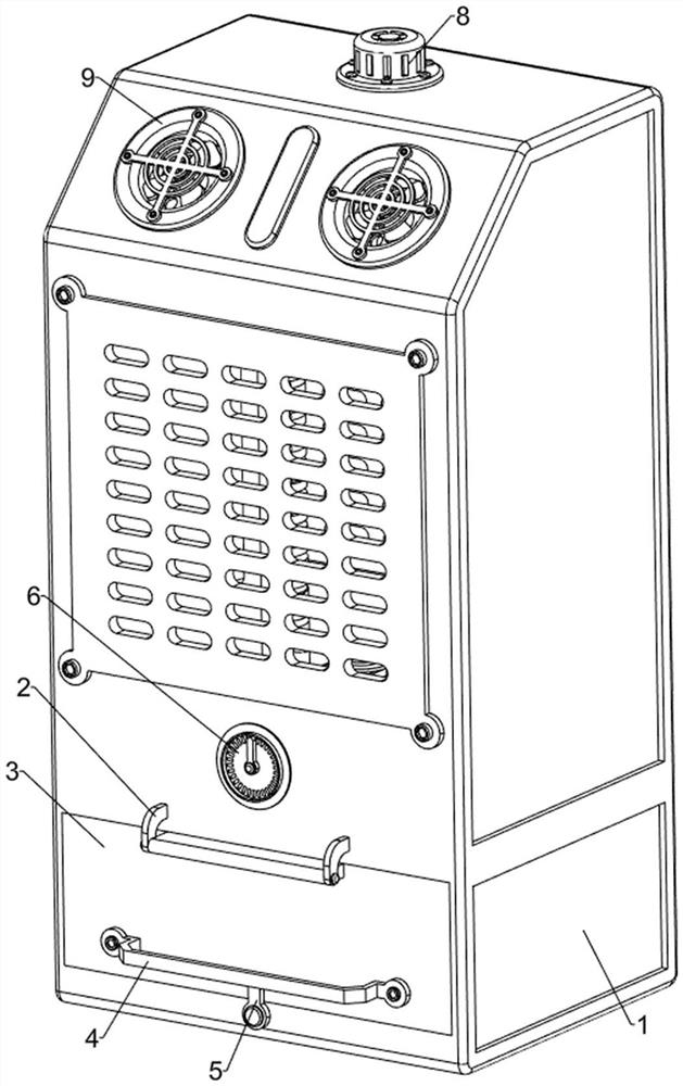
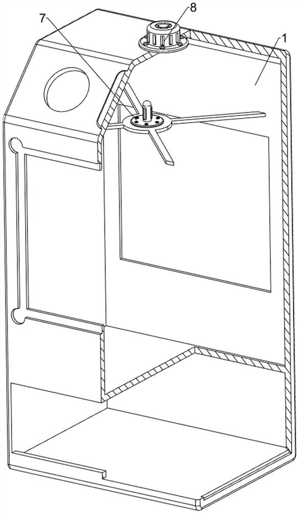
[0033] A gas leakage monitoring and alarm device for coal mine operations, such as Figure 1 to Figure 5 As shown, it includes a base 1, a first connecting rod 2, a sealed door 3, a handle 4, a limit column 5, a gas parameter disk 6, a test probe 7, a buzzer 8, an air extraction mechanism 9 and an ash removal mechanism 10 The front side of the lower part of the base 1 is provided with a first connecting rod 2, and a sealed door 3 is hinged on the first connecting rod 2. The sealed door 3 fits with the placement opening opened on the front side of the base 1. Hand 4, the bottom of the front side of the base 1 is provided with a limit column 5, the front side of the middle part of the base 1 is provided with a gas parameter plate 6, the test probe 7 is connected between the inner side of the upper part of the base 1, the buzzer 8 is provided on the top of the base 1, and the base 1 An air extraction mechanism 9 is arranged on the front side, and an ash removal mechanism 10 is ar...
Embodiment 2
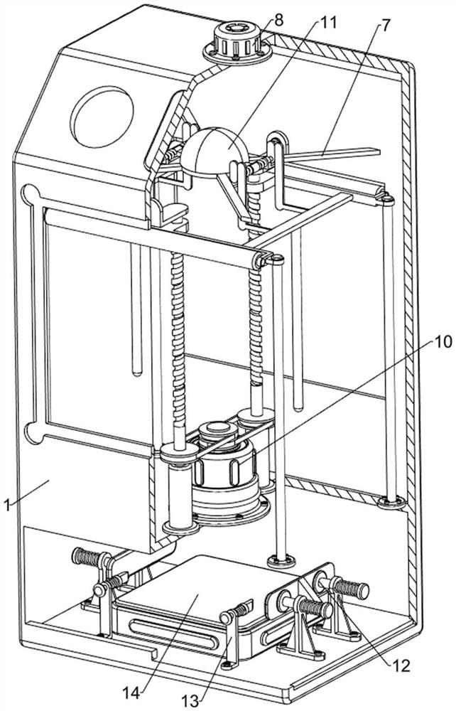
[0038] On the basis of Example 1, such as figure 2 , Image 6 and Figure 7 As shown, a protective mechanism 11 is also included, and the protective mechanism 11 includes a mounting frame 111, a protective plate 112, a torsion spring 113, a first contact plate 114, a second contact plate 115 and a second connecting rod 116, and the left and right sides of the test probe 7 Mounting frame 111 is provided on each side, and first contact plate 114 is arranged on the mounting frame 111 in a rotating manner. Protective plate 112 is provided on the first contact plate 114. A torsion spring 113 is connected between the connecting brackets 106, and a second connecting rod 116 is symmetrically connected between the connecting brackets 106. The inner side of the second connecting rod 116 is provided with a second contact plate 115, and the second contact plate 115 is connected to the adjacent first contact plate. 114 fits.
[0039] In order to prevent the test probe 7 from being dama...
Embodiment 3
[0041] On the basis of Example 2, such as figure 2 , Figure 8 to Figure 12 As shown, it also includes a limit mechanism 12 on both sides of the tester, and the limit mechanism 12 on both sides of the tester includes a mounting bracket 121, a limit plate 122, a first return spring 123, a guide column 124, a first wedge block 125 and The lower pressure column 126, the left and right sides of the inner bottom of the base 1 are symmetrically provided with mounting brackets 121, the upper part of the mounting bracket 121 is slidingly provided with guide columns 124, and the inner sides of the two guide columns 124 on the same vertical side are connected within a limited range. The position plate 122, the guide post 124 are all connected with the first return spring 123 between the outside of the mounting bracket 121, the outside of the limit plate 122 is provided with a first wedge block 125, and the bottom of the second connecting rod 116 is provided with a pressing post 126 . ...
PUM
 Abstract
Description
Claims
Application Information
 - R&D
- Intellectual Property
- Life Sciences
- Materials
- Tech Scout
- Unparalleled Data Quality
- Higher Quality Content
- 60% Fewer Hallucinations
Browse by: Latest US Patents, China's latest patents, Technical Efficacy Thesaurus, Application Domain, Technology Topic, Popular Technical Reports.
© 2025 PatSnap. All rights reserved.Legal|Privacy policy|Modern Slavery Act Transparency Statement|Sitemap|About US| Contact US: help@patsnap.com