Arbitrary interval linear array end-fire enhanced phase configuration method
A linear array and configuration method technology, applied in the field of array antennas, can solve the problem of low directivity coefficient of ordinary end-fire, achieve the effect of reducing precision requirements and processing difficulty, and reducing sensitivity
- Summary
- Abstract
- Description
- Claims
- Application Information
AI Technical Summary
Problems solved by technology
Method used
Image

Examples
Embodiment A6
[0066] Embodiment A.6 element equally spaced linear array
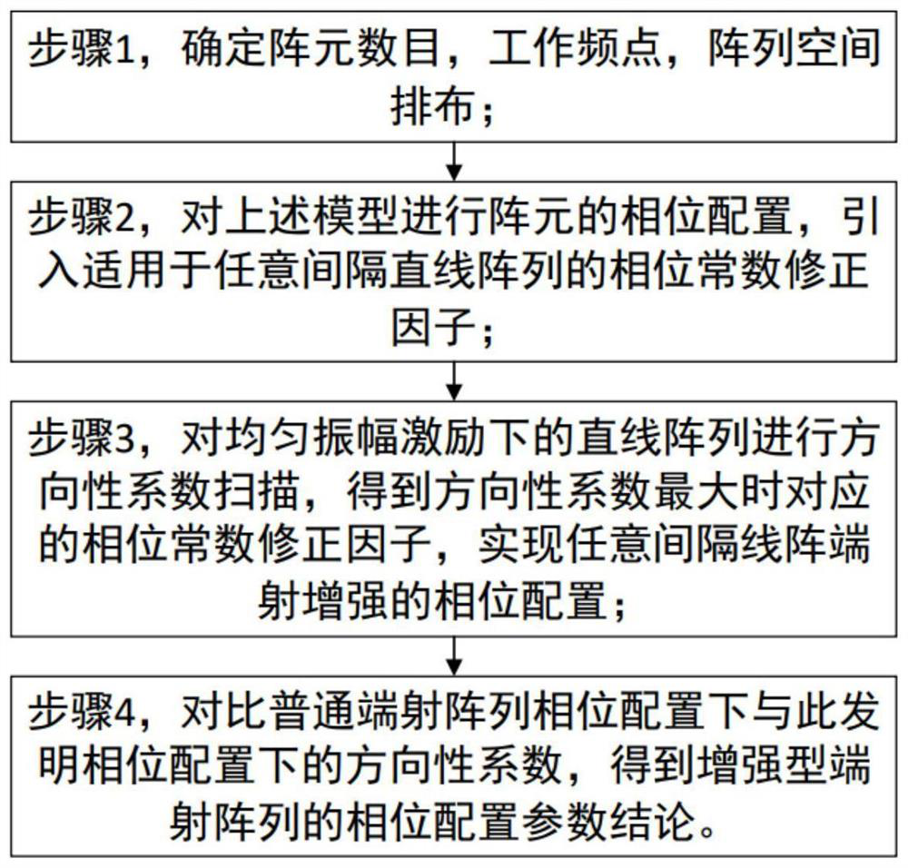
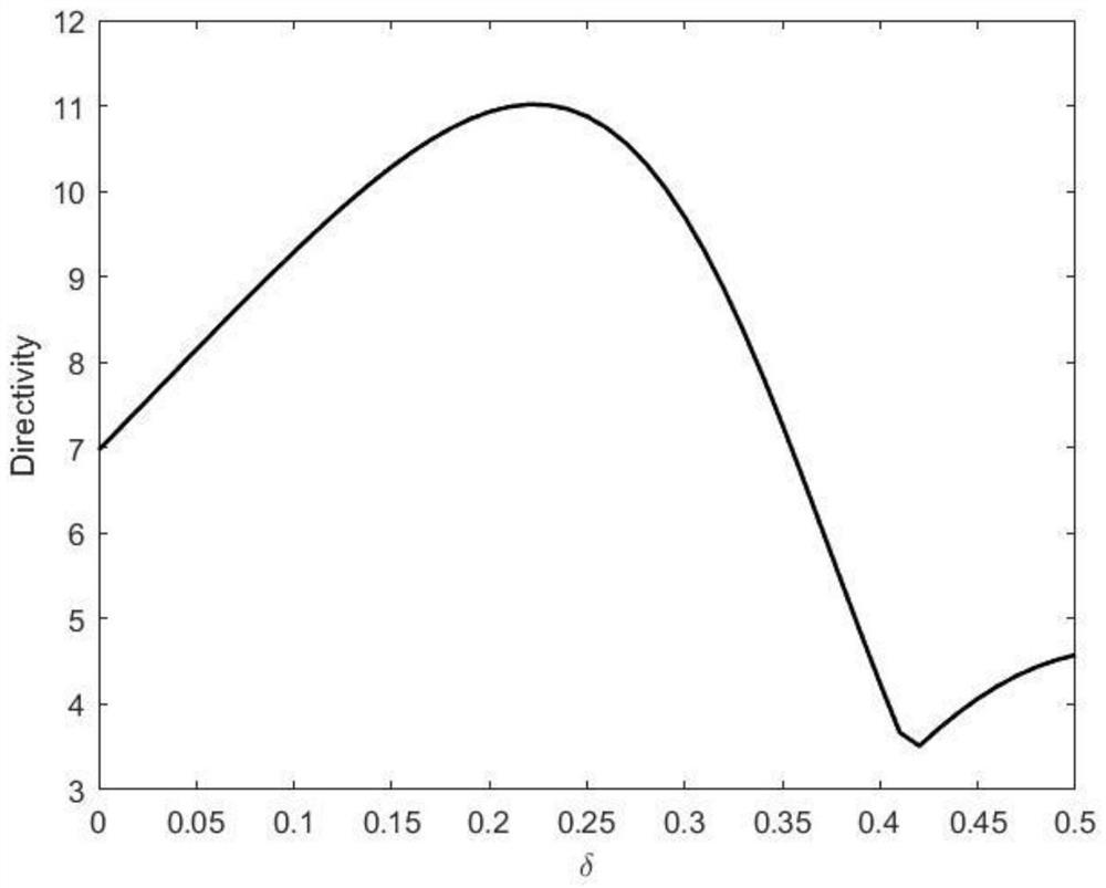
[0067] The arrangement of array elements satisfies interval The amplitude excitation of the array element is I n =1, the phase excitation is α n =β(1+δ)Z n , where the spacing common ratio k=1.1, and the space angle scanning step is set to 1°. See figure 2 , Schematic diagram of the phase correction factor scanning of the embodiment of the six-element equal-ratio spaced linear array, the correction factor is scanned in the range of 0<δ<0.5, and the correction factor scanning step is set to 0.01. For an ideal omnidirectional radiation array element, within the correction factor scanning range Two extremum points are obtained successively from 0 in the positive interval of , and their physical meanings are respectively the maximum directivity coefficient corresponding to the optimal correction factor value; the phase correction factor end-fire array condition critical value.
[0068] When the value of the corre...
Embodiment C
[0074] Example C. 6-element sparse linear array
[0075] A 6-element sparse linear array is designed so that the distance between the array elements is greater than half the wavelength, and the grating lobes are eliminated in the visible region. refer to Figure 8 , Schematic diagram of the position of the array element of the six-element sparse linear array, the position of the array element is Z n =[0; 0.831λ; 1.331λ; 1.910λ; 2.563λ; 3.5λ], the amplitude excitation of the array element is I n =1, the phase excitation is α n =β(1+δ)Z n , set the space angle scan step to 1°.
[0076] refer to Figure 9 , Schematic diagram of scanning the phase correction factor of the embodiment of the six-element sparse linear array, the correction factor is scanned in the range of 0<δ<0.3, and the scanning step of the correction factor is set to 0.01. When the correction factor is 0.06, when the maximum directivity coefficient is reached, the directivity coefficient of the correspondin...
Embodiment A
[0081] Table embodiment A, B, C parameter comparison
[0082] Through the parameter comparison tables of Examples A, B, and C, it can be concluded that this method has slightly different optimization effects on linear arrays with different intervals, but still has two advantages of high efficiency and universal applicability. In embodiment C, the array spacing is first determined through genetic algorithm optimization, and then the phase constant correction factor is used to realize the super-directional optimization of the array with a spacing greater than half a wavelength. Compared with other existing super-directional optimization methods in the field of array antennas, this method optimizes the array element with uniform amplitude excitation, which reduces the sensitivity of excitation configuration in practical applications, and reduces the processing difficulty and accuracy requirements.
PUM
 Abstract
Description
Claims
Application Information
 - R&D
- Intellectual Property
- Life Sciences
- Materials
- Tech Scout
- Unparalleled Data Quality
- Higher Quality Content
- 60% Fewer Hallucinations
Browse by: Latest US Patents, China's latest patents, Technical Efficacy Thesaurus, Application Domain, Technology Topic, Popular Technical Reports.
© 2025 PatSnap. All rights reserved.Legal|Privacy policy|Modern Slavery Act Transparency Statement|Sitemap|About US| Contact US: help@patsnap.com