Feeding and discharging system and method for intelligent machining of copper bars

A technology of intelligent processing and copper bars, which is applied to the improvement of process efficiency, mechanical conveyors, conveyor objects, etc., can solve problems such as scratches on the surface of copper bars, misjudgment of copper bars, and failure of normal grasping of porous copper bars. To achieve the effect of ensuring the grasping effect and improving safety

Pending Publication Date: 2022-05-20
无锡中车时代智能装备研究院有限公司
View PDF9 Cites 0 Cited by
  • Summary
  • Abstract
  • Description
  • Claims
  • Application Information

AI Technical Summary

Problems solved by technology

[0005] In order to solve the deficiencies of the existing technology, the purpose of the invention is to provide a method and system for loading and unloading that cooperate with the unmanned intelligent production line of copper bars, so as to solve the problem that the manual handling in the prior art is labor-intensive and easily scratches the surface of the copper bars. , the problem that porous copper bars cannot be grasped normally and manual misjudgment of different types of copper bars

Method used


Image

  • Feeding and discharging system and method for intelligent machining of copper bars
  • Feeding and discharging system and method for intelligent machining of copper bars
  • Feeding and discharging system and method for intelligent machining of copper bars

Examples


Embodiment 2

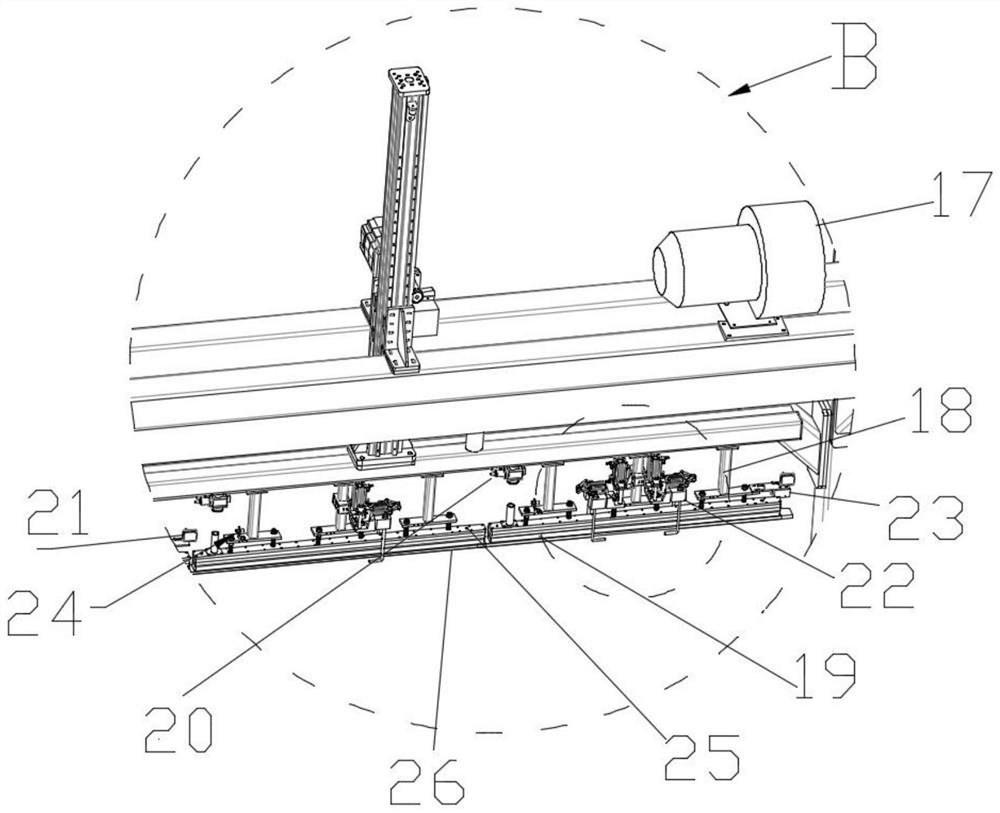
[0043] Different from Embodiment 1, an elastic buffer assembly 27 is also provided between the vertical connecting rod 18 and the suction cup 19, and the elastic buffer assembly 27 includes a buffer plate 271 and a connection buffer pad arranged at the lower end of the vertical connecting rod. The buffer spring 272 of the plate and the suction cup is used to slow down the impact force when the suction cup is in contact with the copper bar, so as to avoid damage to the copper medal.

Embodiment 3

[0045] The difference from Embodiment 1 is that a code scanning device 23 is provided at the outer end of the suction cup 19, and the scanning camera of the code scanning device is just aligned with the bar code on the copper plate, and the identity of the copper bar is identified by the bar code system to realize the traceability of the whole process.

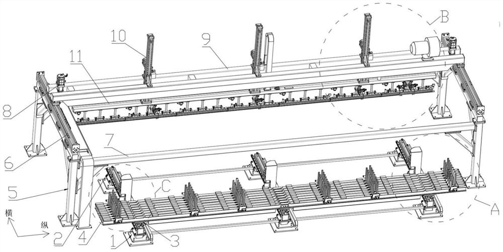
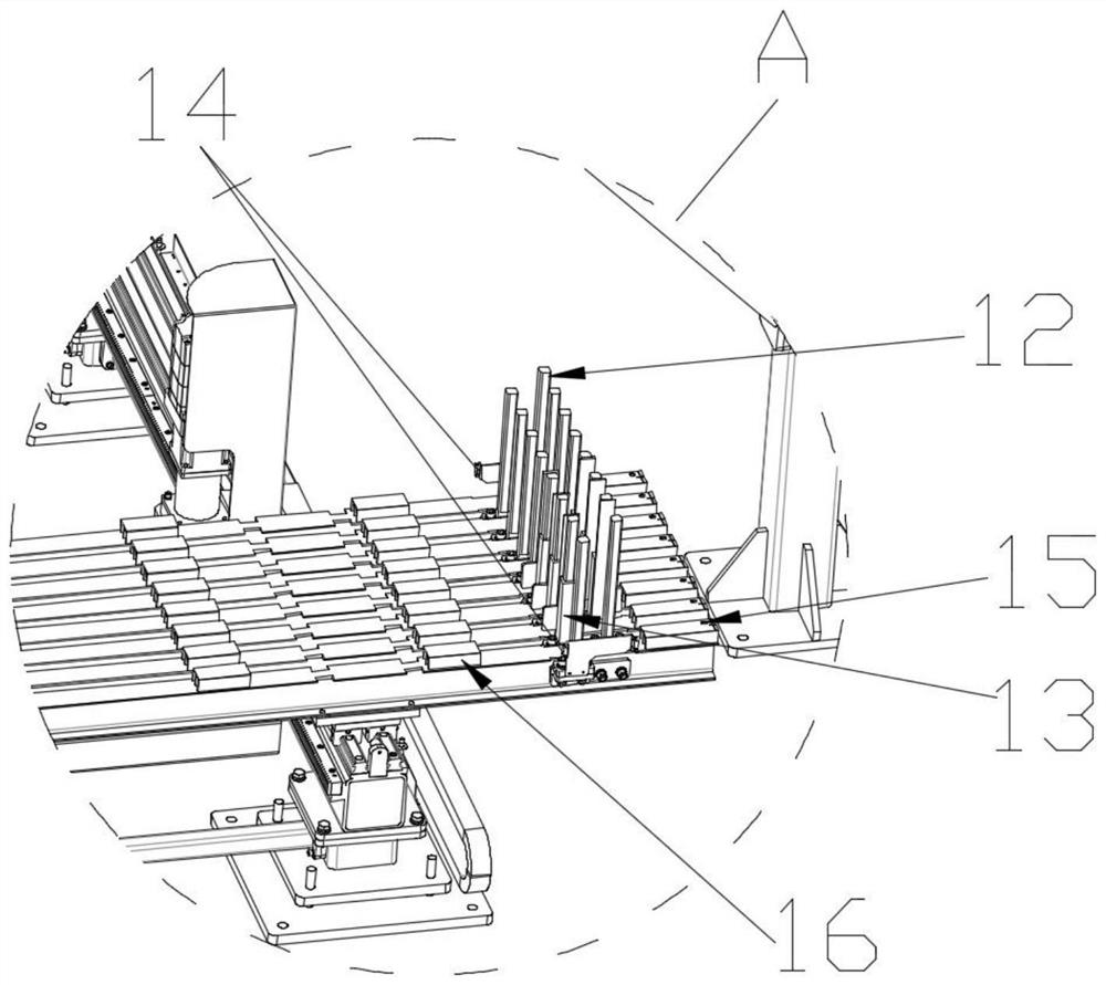
[0046] The beam silo 4 is also provided with a boss 16 made of channel steel. Because the manual feeding uses a sling to directly load the material, the copper bar will crush the sling and cannot be pulled out. A certain number of bosses are installed on the silo. 16 can provide the gap between the support boss and the boss for the copper bar to take out for the suspenders.

[0047] The above-mentioned loading and unloading method of the loading and unloading system for intelligent processing of copper bars includes the following steps:

[0048] Step 1. In the factory, when copper bars 26 (or other materials) need to be added ...


PUM


Abstract

The invention discloses a feeding and discharging system for intelligent machining of a copper bar. The feeding and discharging system comprises a copper bar skip car, a truss manipulator body, a vacuum suction cup system and a control device. The copper bar skip car comprises a bottom supporting leg, an x-axis transverse guide rail, a skip car supporting plate and a cross beam stock bin, the bottom supporting leg stably supports the trolley, the x-axis transverse guide rail is erected on the bottom supporting leg, and the skip car supporting plate is erected on the x-axis transverse guide rail and can slide on the x-axis transverse guide rail under the driving of external force; the vacuum suction cup system comprises a fan, a vertical connecting rod, a suction cup, a valve set and a gripper assembly used for preventing a copper bar from falling off. The fan is erected on the longitudinal moving beam and connected with the longitudinal air cylinder through an air pipe. The suction cup is connected with the longitudinal air cylinder through a vertical connecting rod. The control device is used for controlling the action of the copper bar skip car, the truss manipulator body and the action part of the vacuum chuck system; automatic feeding and discharging can be achieved, the copper bars are not damaged, fall or lost, the identity of the copper bars can be traced in the whole process, and safety is high.

Description

technical field [0001] The invention belongs to the field of copper bar processing, in particular to a loading and unloading system and method for intelligent processing of copper bars. Background technique [0002] In the production and processing of large generators, the processing of rotor windings is the main processing step, but the length of rotor windings of different types of motors has a large span (2m-10m). For the loading and unloading requirements of copper bars, a method and system for loading and unloading copper bars for intelligent processing is now designed. [0003] At present, in the existing processing production line, the feeding of copper bars and the circulation of each station are mostly operated manually, mainly by crane hoisting and transportation. [0004] The labor intensity of workers during this process is high, and copper bars of different types and sizes are mostly obtained by manual naked eye identification or measuring tools, which is prone...

Claims


Application Information

Patent Timeline
Patent Type & Authority Applications(China)
IPC IPC(8): B65G35/00B65G47/91B65G43/08
CPCB65G35/00B65G47/914B65G43/08Y02P10/20
Inventor 严思杰徐勤祥刘一航李克宁刘星郑志伟孙宇
Owner 无锡中车时代智能装备研究院有限公司
Why Eureka
Try Eureka