Hot air blowing dryer capable of circularly heating

A technology of circulating heating and drying machine, applied in the direction of drying machine, drying, heating device, etc., can solve the problems of poor air supply effect, inconvenient dehumidification, and inability to realize circulating air supply by wind force.

Pending Publication Date: 2022-05-20
江苏云康电热设备有限公司
View PDF0 Cites 0 Cited by
  • Summary
  • Abstract
  • Description
  • Claims
  • Application Information

AI Technical Summary

Problems solved by technology

[0003] However, during the use of the existing dryers, dehumidification is more troublesome during the dehumidification process of circulation conduction, which is easy to cause repeated drying, and the wind force cannot realize the circulating air supply during the hot air supply process, which makes the ai

Method used


Image

  • Hot air blowing dryer capable of circularly heating
  • Hot air blowing dryer capable of circularly heating
  • Hot air blowing dryer capable of circularly heating

Examples


Embodiment 1

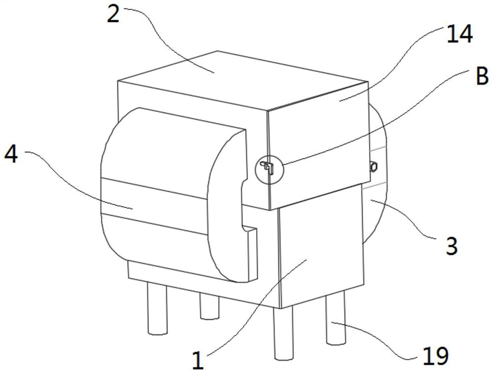
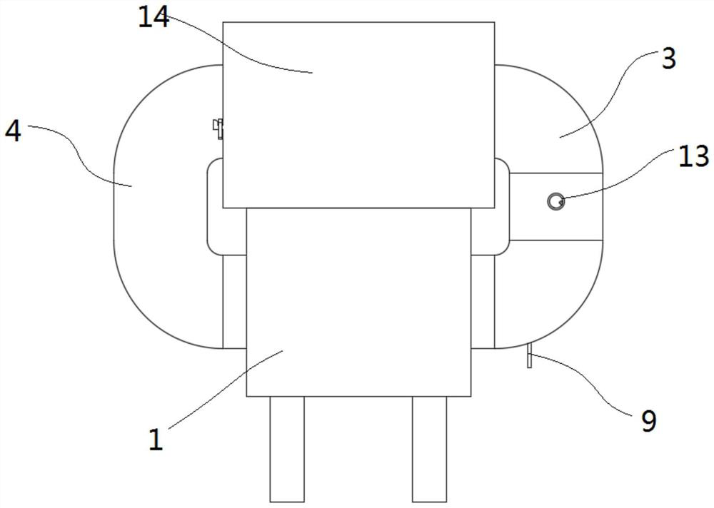
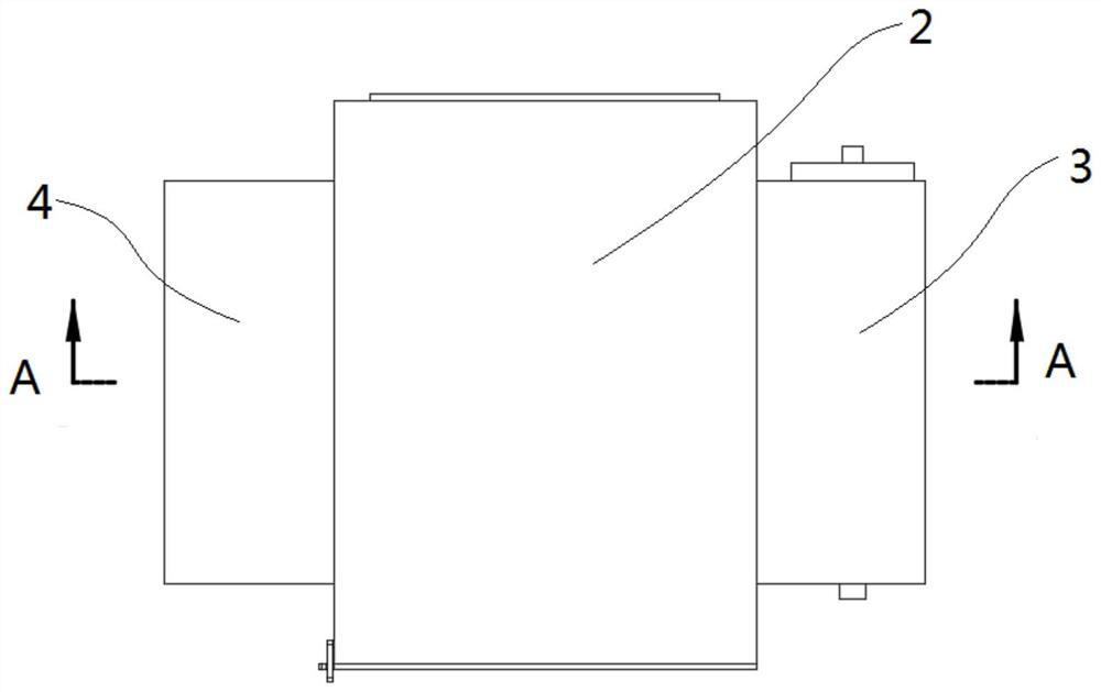
[0033] Please refer to Figure 1-5 As shown, the present invention is a hot air blowing dryer for circulating heating, including a lower casing 1, an upper casing 2, a first air duct 3 and a second air duct 4 oppositely arranged on the side of the lower housing 1 , the dehumidifying assembly arranged in the first air duct 3, and the second air duct 4 is provided with a constant flow fan 12;

[0034] The upper casing 2 is located directly above the lower casing 1, and the upper casing 2 and the side of the lower casing 1 are provided with air duct openings. The first air duct 3 and the second air duct 4 have a C-shaped structure, and the first air duct The upper and lower ends of the channel 3 and the second air channel 4 are connected through the air channel opening;

[0035] The dehumidifying assembly includes water tanks 5 relatively arranged on both sides of the first air channel 3. The interior of the water tanks 5 is hollow, and a number of condensation water pipes 6 are...

Embodiment 2

[0046] Such as Figure 9 as shown, Figure 9 It is a schematic diagram of the overall structure of the drying box in Embodiment 2 of the present invention. The difference from Embodiment 1 is that the bottom and side walls of the drying box 16 are provided with a number of strip-shaped through holes in an array. This embodiment is mainly used for drying. Dry the material with a slightly larger volume, and the material will not fall off from the strip-shaped through-hole. The setting of the strip-shaped through-hole increases the direct contact area between the material and the hot air, which facilitates the evaporation of moisture in the material and facilitates the drying of the material.


PUM


Abstract

The invention discloses a hot air blowing dryer capable of circularly heating, and relates to the technical field of dryers, the hot air blowing dryer comprises a shell, an upper shell, a first air duct and a second air duct which are oppositely arranged at the side part of the lower shell, and a dehumidification assembly arranged in the first air duct, and a constant flow fan is arranged in the second air duct; the dehumidifying assembly comprises water tanks oppositely arranged on the two sides of the first air channel, the water tanks are hollow, a plurality of condensate pipes are connected between the water tanks in a penetrating mode and distributed in an equally-spaced array mode, a water receiving groove is formed in the lower end of each condensate pipe and obliquely arranged, and an included angle is formed between each water receiving groove and the corresponding condensate pipe. One end of the water receiving groove is connected with a water receiving box in a penetrating mode, the side wall of the water receiving box is connected with the side wall of the water tank, the lower end of the water receiving box is connected with a water outlet pipe in a penetrating mode, and the water outlet pipe penetrates through the lower wall of the first air channel. The hot air blowing dryer capable of circularly heating has the advantage of being good in drying effect.

Description

technical field [0001] The invention relates to the technical field of dryers, in particular to a hot air purging dryer capable of circulating heating. Background technique [0002] Dryers can be divided into industrial and civilian. Industrial dryers are also called drying equipment or dryers. Civilian dryers are one of washing machines. They are generally used to remove clothing and other textiles after washing and dehydration. The dryer has several modes such as belt drying, drum drying, box drying, tower drying, etc.; the heat source includes coal, electricity, gas, etc.; the material has hot air flow and airflow during the drying process. Radiant type, etc., hot air drum drying is that the hot air flow moves forward from the tail, fully contacts with the material, and makes full use of the heat transfer through heat conduction, convection, and radiation; the heat energy is directly transferred to the material, so that the moisture of the material is continuously evapora...

Claims


Application Information

Patent Timeline
IPC IPC(8): F26B21/00F26B21/04F26B23/04F26B9/06F26B25/00
CPCF26B21/001F26B21/04F26B23/04F26B9/06F26B25/005F26B25/00Y02P70/10
Inventor 周玲
Owner 江苏云康电热设备有限公司
Why Eureka
Try Eureka