A heat pump drying system with dehumidification and waste heat utilization

A heat pump drying and hot-end technology, which is applied to machines that use waste heat, drying, heat pumps, etc., can solve the problems of reducing energy loss, excessive equipment, wasting waste heat, etc., to improve recycling rate, strengthen dehumidification effect, simplify structure effect

Active Publication Date: 2017-12-19
广州润达环保科技有限公司
View PDF11 Cites 0 Cited by
  • Summary
  • Abstract
  • Description
  • Claims
  • Application Information

AI Technical Summary

Problems solved by technology

[0002] The working principle of the traditional dryer is to convert the outside air into high-temperature air after being heated by the heating device, and then supply the high-temperature air to a relatively closed space to dry the objects, and then the high-temperature and high-humidity air will be discharged after the drying is completed. , this method has very low energy efficiency, so most of the current drying equipment uses heat pumps for heating and drying, thereby reducing energy loss
However, a large amount of moisture is still produced in the drying environment, so it is necessary to discharge it directly or use a dehumidifier to extract the moisture, so the residual heat in the air will be discharged together, and the heated air will There are impurities or harmful gases, and it needs to be discharged regularly to keep the indoor air environment safe and clean, but direct pumping will waste a lot of waste heat, and the utilization rate of heat energy is low, so it needs to be improved
There are some drying devices that dehumidify and recover waste heat at the same time. They add an internal circulation dehumidifying evaporator to the heat pump cycle system. When dehumidifying, by switching the refrigerant channel, the air evaporator stops running, and the dehumidifying evaporator and condensation The refrigerant cycle is formed with the compressor and the throttle valve. This structure needs to be completed through a complex refrigerant cycle system and control system. There are many equipments and large investment, and the effect of dehumidification and waste heat recovery is not ideal.

Method used


Image

  • A heat pump drying system with dehumidification and waste heat utilization
  • A heat pump drying system with dehumidification and waste heat utilization
  • A heat pump drying system with dehumidification and waste heat utilization

Examples


Embodiment Construction

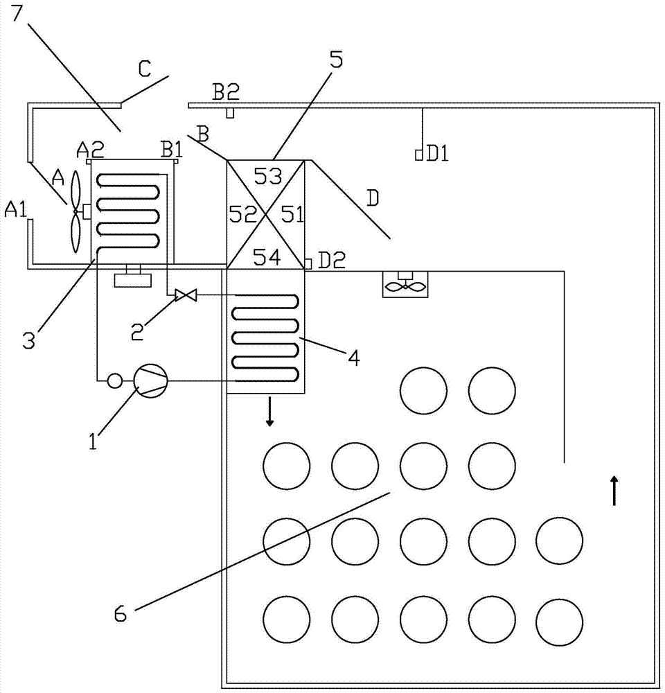
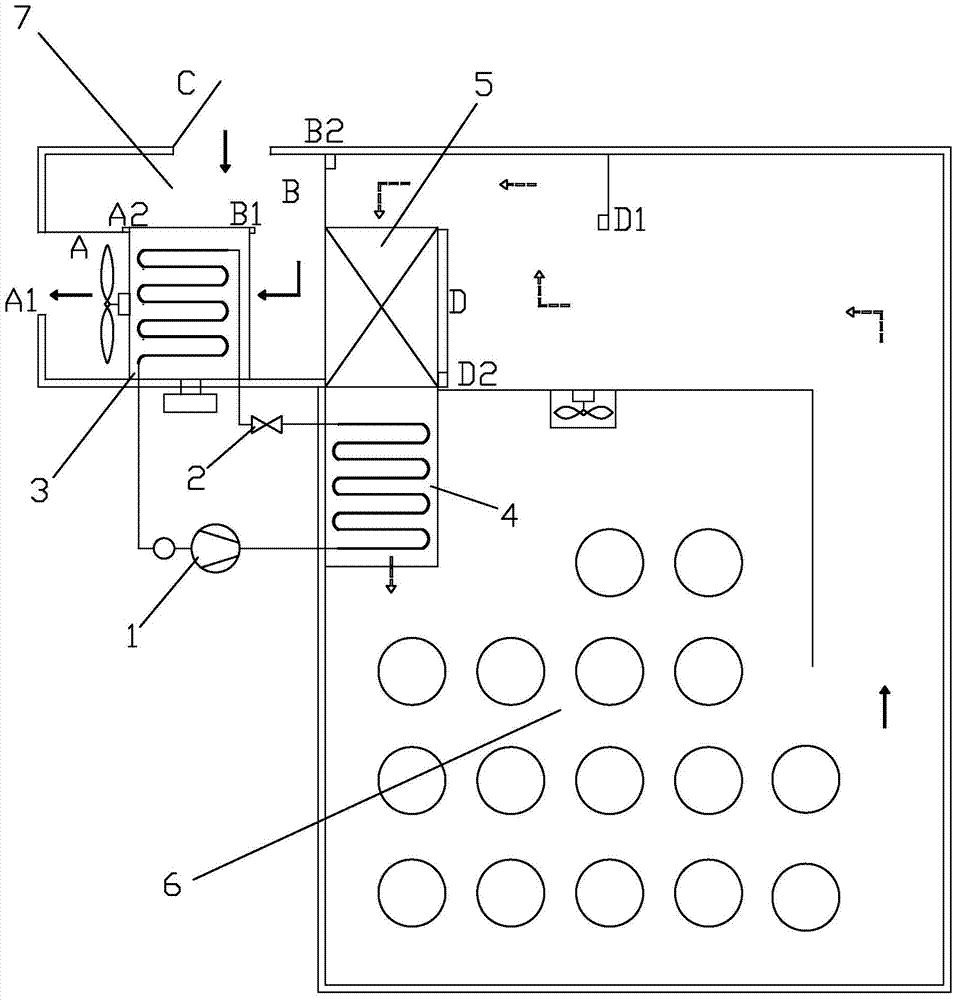
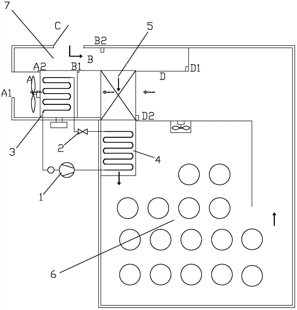
[0017] refer to figure 1 , a heat pump drying system with dehumidification and waste heat utilization of the present invention, and a switchable air duct, including a compressor 1, a condenser 4, an evaporator 3, a throttling element 2, and an enhanced dehumidification effect and heat recovery The effect of the heat exchanger 5, the condenser 4 is installed in the drying room 6, the compressor 1, the throttling element 2 and the evaporator 3 partition wall are installed outdoors or other locations and the refrigerant pipes are connected to the condenser 4 connected, the evaporator 3 and the heat exchanger 5 are installed in a controllable air duct 7, the heat exchanger 5 is located at the central position of the air duct 7, and the air duct 7 is provided with at least two controllable air inlet and outlet ports for heat exchange The air inlet 51 of the first heat exchange end of the device 5 is controllably communicated with the drying room 6 through the air duct 7, and the ai...


PUM


Abstract

The invention discloses a heat pump drying system having dehumidification and waste heat utilization functions. The heat pump drying system comprises a compressor, a condenser, a throttling element, an evaporator and a heat exchanger for enhancing the dehumidification effect and the heat recovery effect. The compressor, the condenser, the throttling element and the evaporator are connected through a refrigerant pipe. The condenser is mounted in a drying room. The evaporator and the heat exchanger are both mounted in a controllable air duct. The air duct is provided with a controllable air inlet and a controllable air outlet. An air inlet of the first heat exchange end of the heat exchanger is controllably communicated with the drying room through the air duct. An air inlet of the second heat exchange end of the heat exchanger is controllably connected with the drying room or the air inlet of the air duct through the air duct. An air outlet of the second heat exchange end of the heat exchanger is connected with an air inlet of the condenser. An air inlet of the evaporator is controllably connected with the air inlet of the air duct or an air outlet of the first heat exchange end of the heat exchanger through the air duct. According to the system, the structure of the drying system is greatly simplified, and equipment investment is reduced; moreover, the heat energy recovery rate is effectively increased, and the dehumidification effect is greatly enhanced.

Description

technical field [0001] The invention relates to a heat pump drying system with dehumidification and waste heat utilization. Background technique [0002] The working principle of the traditional dryer is to convert the outside air into high-temperature air after being heated by the heating device, and then supply the high-temperature air to a relatively closed space to dry the objects, and then the high-temperature and high-humidity air will be discharged after the drying is completed. , This method has very low energy efficiency, so most of the current drying equipment uses heat pumps for heating and drying, thereby reducing energy loss. However, a large amount of moisture is still produced in the drying environment, so it is necessary to discharge it directly or use a dehumidifier to extract the moisture, so the residual heat in the air will be discharged together, and the heated air will Containing impurities or harmful gases, it needs to be discharged regularly to keep ...

Claims


Application Information

Patent Timeline
Patent Type & Authority Patents(China)
IPC IPC(8): F26B21/00F26B21/08F25B30/02F25B27/02
CPCY02A30/274Y02P70/10
Inventor 平武臣
Owner 广州润达环保科技有限公司
Why Eureka
Try Eureka