Lumbar vertebra posterior zero-incisura fusion cage, driving-in system and driving-in method

A cage, zero-notch technology, used in spinal implants, joint implants, joint implants, etc., can solve problems such as difficulty, large trauma, affecting sight, and achieve the effect of stable position

Pending Publication Date: 2022-05-24
黄振强
View PDF1 Cites 0 Cited by
  • Summary
  • Abstract
  • Description
  • Claims
  • Application Information

AI Technical Summary

Problems solved by technology

The application of the anterior lumbar zero-profile fusion device has also been carried out in foreign countries, but the disadvantages of the anterior lumbar fusion device are: decompression of the spinal canal, after discectomy, another anterior incision is required to place the fusion device, and the trauma is relatively large. Big
However, the practical application is more difficult than the anterior lumbar approach. For example, a posterior lumbar intervertebral fusion system disclosed in Chinese invention patent CN109806034A, and a fusion device is placed in the posterior lumbar spine. The venous plexus, fat tissue, residual fibrous ring, and proliferative osteophyte tissue block the line of sight, and it is almost impossible to insert the fusion cage into the intervertebral space and then install the locking nail.

Method used


Image

  • Lumbar vertebra posterior zero-incisura fusion cage, driving-in system and driving-in method
  • Lumbar vertebra posterior zero-incisura fusion cage, driving-in system and driving-in method
  • Lumbar vertebra posterior zero-incisura fusion cage, driving-in system and driving-in method

Examples


Embodiment 1

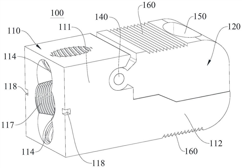
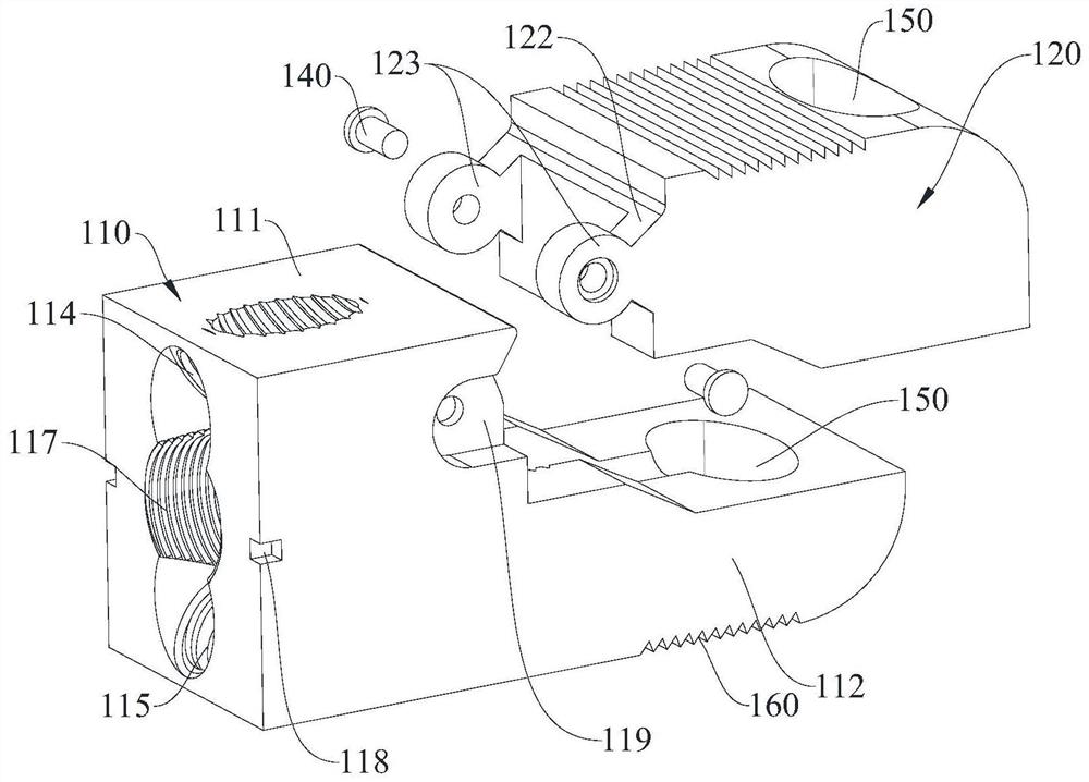
[0054] Please refer to Figure 1-9 , Embodiment 1 of the present invention provides a posterior lumbar spine zero-notch fusion cage, which includes a fixed part 110 and a spreader part 120, the spreader part 120 is rotatably connected to the upper part of the side of the fixed part 110, so as to be relatively The fixing portion 110 rotates. The fixing part 110 is used for locking on the upper vertebral body and the lower vertebral body of the lumbar vertebrae, and the spreading part 120 is used for upwardly spreading so that the upper side of the cage 100 has an upward slope, that is, when the cage 100 is opened, After entering between the upper vertebral body and the lower vertebral body of the lumbar vertebrae, the stretching portion 120 is propped up by opening the screw to rotate relative to the fixing portion 110, so that the upper vertebral body is stretched and abutted upward and the upper vertebral body is pushed up. the front column, and the fixing part 110 is locked...

Embodiment 2

[0072] like Figure 12-17 As shown, Embodiment 2 of the present invention provides a system for driving a posterior lumbar vertebrae with zero-notch fusion device, which includes a driving device and the fusion device shown in Embodiment 1.

[0073] like Figure 12-16 As shown, the driver 200 includes a sleeve 230 , a head 210 and a hollow screw 220 with a tail cap 240 . The head 210 is detachably connected to the cage 100, so as to connect the cage 100 through the head 210, and then drive it between the upper vertebral body and the lower vertebral body. A through hole 211 is formed in the middle of the head 210 . The head is connected with the sleeve 230, and a through hole 211 is opened in the middle of the head, which communicates with the sleeve 230 and is coaxially arranged; the hollow screw is sleeved on the sleeve 230 and passes through In the hole 211, one end of the hollow screw close to the end cap 240 is threadedly connected to the sleeve 230, and the end of the ...

Embodiment 3

[0081] like Figure 18-22 As shown, Embodiment 3 of the present invention provides an application method of the fusion device 100, that is, an insertion method, which includes the following steps:

[0082] After the decompression of the spinal canal in the posterior lumbar vertebrae and the resection of the intervertebral disc are completed, the cage and the driver are detachably connected into one body, and then the cage is driven into the upper vertebral body and the lower vertebral body from the posterior lumbar vertebra. The opening part of the cage faces the side of the upper vertebral body; the opening pin is passed through the driver into the cage, and abuts the opening part to make it open upward Abutting and pushing up the anterior column of the upper vertebral body, the spreading portion is stretched to a preset height and then stops screwing in the spreading pin; the fixing portion of the cage is locked by the locking pin 170 Within the upper and lower vertebral bo...


PUM

PropertyMeasurementUnit
Outer diameteraaaaaaaaaa

Abstract

The invention discloses a lumbar vertebra posterior zero-incisura fusion cage, a driving-in system and a driving-in method. After the fusion cage is driven into the intervertebral body, the distraction angle of the distraction part rotationally connected to the fusion cage fixing part is controlled through the screwing-in depth of the distraction nail, and the selected-in depth of the distraction nail can be selected according to the actual situation requirement so as to meet the distraction height of different intervertebral bodies; meanwhile, the fusion cage is opened on one side, namely, the opening part is opened towards one side of the upper vertebral body, and after opening, compared with a fusion cage located on one side of the anterior vertebral body, the fusion cage located on one side of the posterior vertebral body can stably and effectively jack up the anterior column of the upper vertebral body upwards so that the anterior column of the upper vertebral body can recover the physiological camber of the anterior column of the upper vertebral body. Moreover, the fixing parts of the fusion cage are respectively locked on the upper vertebral body and the lower vertebral body through the lock nails, so that the expanded fusion cage is prevented from shifting, the problem of shifting of the fusion cage caused by the extrusion of the vertebral body during the movement of a human body after an operation is avoided, and the position of the fusion cage between the vertebral bodies is kept stable and unchanged.

Description

technical field [0001] The invention relates to the technical field of posterior lumbar vertebra implantation, in particular to a zero-notch fusion device for the posterior lumbar vertebra, an insertion system and an insertion method. Background technique [0002] Lumbar fusion cage is a kind of: after spinal canal decompression and intervertebral disc resection, in order to restore the normal height of the intervertebral space and the physiological curvature of the lumbar spine, so that the upper and lower vertebral bodies can be more stably fused together after the removal of the intervertebral disc. Devices implanted in the body. [0003] In the early stage, only the cage was implanted, and the cage slipped into the spinal canal after surgery. Now the routine practice is: after implanting the cage, the upper and lower pedicle screw rods are also added for fixation. This approach greatly reduces the postoperative slippage of the cage, and also significantly improves the ...

Claims


Application Information

Patent Timeline
IPC IPC(8): A61F2/44A61F2/30A61F2/46
CPCA61F2/4455A61F2/30749A61F2/4611A61F2002/30518A61F2002/30556A61F2002/30579A61F2002/30622A61F2002/30754A61F2310/00023A61F2002/4681
Inventor 黄振强黄嘉明
Owner 黄振强
Why Eureka
Try Eureka