Tool clamp for pipeline laser cutting machine and pipeline laser cutting machine

A technology of laser cutting machine and fixture, applied in the direction of manufacturing tools, household appliances, other household appliances, etc., can solve the problems of complicated operation, transfer pipes, repositioning pipes, etc., and achieve the effect of high availability and simple operation.

Active Publication Date: 2022-05-24
中交三航(南通)海洋工程有限公司
View PDF23 Cites 0 Cited by
  • Summary
  • Abstract
  • Description
  • Claims
  • Application Information

AI Technical Summary

Problems solved by technology

[0004] However, there are still obvious defects in its use: 1. For laser cutting machines with different precision and different power, there may be burrs at the incisions of the pipes, which need to be manually polished one by one. , or with the help of other equipment for subsequent processing, not only the operation is cumbersome, but also the subsequent grinding needs to transfer the pipe and reposition the pipe, which is inefficient; After identification, the multi-section pipes produced after cutting may have defective parts, resulting in a decrease in overall product quality and a huge waste of pipe materials, which needs to be improved

Method used


Image

  • Tool clamp for pipeline laser cutting machine and pipeline laser cutting machine
  • Tool clamp for pipeline laser cutting machine and pipeline laser cutting machine
  • Tool clamp for pipeline laser cutting machine and pipeline laser cutting machine

Examples


Embodiment 1

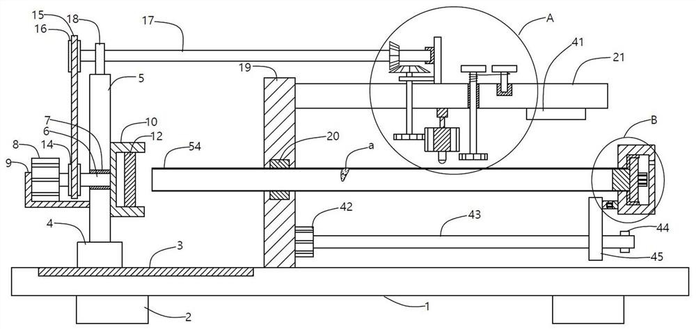
[0032] A tooling fixture for a pipeline laser cutting machine, comprising a base plate 1, a support base 2 is symmetrically fixed at the bottom of the base plate 1, and a support base 2 of a specific height can be flexibly set, thereby changing the height of the base plate 1, which is convenient for users to clamp The guide rail 3 is embedded in the top surface of the bottom plate 1, and the slider 4 is movably arranged on the guide rail 3. The slider 4 can slide along the guide rail 3, and then adjust the position. A support column 5 is fixedly arranged on the support column 5, a rotating rod 6 is hingedly arranged in the support column 5, one end of the rotating rod 6 is fixed on the output shaft of the first rotating motor 8, and the other end of the rotating rod 6 is fixed with a bearing frame 10, Therefore, when the first rotating motor 8 is started, the bearing frame 10 is driven to rotate by the rotating rod 6, and the bearing frame 10 is fixedly provided with a grinding...

Embodiment 2

[0037] A tooling fixture for a pipeline laser cutting machine, comprising a base plate 1, a support base 2 is symmetrically fixed at the bottom of the base plate 1, a guide rail 3 is embedded in the top surface of the base plate 1, and a slider is movably arranged on the guide rail 3 4. In order to prevent the sliding block 4 from sliding spontaneously, a locking structure can also be added on both sides of the sliding block 4, thereby making the position of the supporting column 5 more stable. The sliding block 4 is fixedly provided with a supporting column 5, and the supporting column 5 A rotating rod 6 is arranged through the middle hinge, a first annular bearing 7 is embedded in the support column 5, and the rotating rod 6 is hingedly arranged in the first annular bearing 7, so the rotating rod 6 can be in the first annular bearing 7. A stable rotation occurs in the middle, so that the rotation of the grinding wheel 12 is also more stable, to avoid shaking, one end of the r...

Embodiment 3

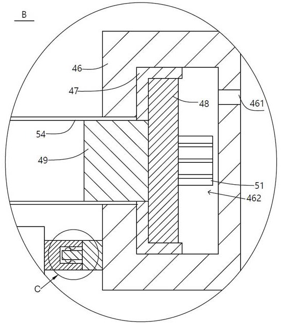
[0042] On the basis of the above-mentioned first or second embodiment, this embodiment further defines and further defines the specific structure of "the positioning block 46 is used for adsorbing and positioning the end of the pipe 54 and can drive the pipe 54 to rotate". It is disclosed, specifically: the positioning block 46 is provided with a ventilation hole 461 and an installation slot 462 that communicate with each other. The setting of the ventilation hole 461 enables the air in the external environment to freely enter and exit the installation slot 462, which is convenient for heat dissipation. The installation slot 462 is hingedly provided with The third annular bearing 47, the end plate 48 is fixedly arranged in the third annular bearing 47, so the end plate 48 can realize stable rotation in the third annular bearing 47, and the elastic inner support pad is fixedly arranged on the end plate 48 49. The diameter of the elastic inner support pad 49 is slightly larger th...


PUM


Abstract

The invention provides a tool clamp for a pipeline laser cutting machine and the pipeline laser cutting machine. The tool clamp comprises a bottom plate, and a grinding wheel is fixedly arranged in a bearing frame; a cleaning sponge is embedded in a clamping groove which is formed in the clamping plate and used for containing a pipeline, a storage box is hinged to a piston shaft of the air cylinder, a marking pen is arranged at the bottom of the storage box in a communicating mode, a linkage rod and a rope winding column are hinged to the interior of the transverse plate, and a marking rope is wound between the linkage rod and the rope winding column. A pipeline defect detector is fixedly arranged at the bottom of the transverse plate; a positioning block is arranged on the nut block in a buckled mode and can drive the pipeline to rotate. According to the tool clamp for the pipeline laser cutting machine and the pipeline laser cutting machine, the end of a pipeline can be polished, whether defects exist in the pipeline or not can be detected, the utilization rate of the pipeline is higher, and the tool clamp is very worthy of popularization.

Description

technical field [0001] The invention relates to the technical field of laser cutting, in particular to a fixture for a pipeline laser cutting machine and a pipeline laser cutting machine. Background technique [0002] As a modern precision machining method, laser cutting uses a focused high-power density laser beam to irradiate the workpiece, so that the irradiated material rapidly melts, vaporizes, ablates or reaches the ignition point, and at the same time, it is blown away by a high-speed airflow coaxial with the beam. Melting substances, thereby cutting the workpiece; laser cutting is one of the thermal cutting methods; compared with traditional processing methods, laser cutting has the advantages of good cutting quality, high cutting efficiency, accurate size, fast cutting speed, strong adaptability and flexibility, The advantages of non-contact cutting process and a wide variety of cutting materials. The cutting quality is superior to other thermal cutting methods, an...

Claims


Application Information

Patent Timeline
Patent Type & Authority Applications(China)
IPC IPC(8): B23K26/38B23K26/70B23K101/06
CPCB23K26/38B23K26/702B23K2101/06Y02P70/10
Inventor 华军明郭静华马嘉阳林凯健陈岳俊
Owner 中交三航(南通)海洋工程有限公司
Why Eureka
Try Eureka