Protective structure of exhaust branch pipe below automobile chassis

A technology for automobile chassis and exhaust branch pipes, which is applied to exhaust devices, vehicle components, and gas intake of power devices, etc., can solve problems such as reducing vehicle power and performance, affecting driving safety, and low gas pressure, and achieving efficient adaptation. performance, ensuring smoothness, and reducing the amount of noise

Pending Publication Date: 2022-05-24
吴飞
View PDF0 Cites 0 Cited by
  • Summary
  • Abstract
  • Description
  • Claims
  • Application Information

AI Technical Summary

Problems solved by technology

[0003] However, when the car is running, especially at high speed, it will produce a large sound wave. Driving on the city streets at night seriously affects the rest of residents. In fact, vehicles with large displacement will choose to install noise reduction devices, and when the vehicle is running at low speed The exhaust pipe will not discharge large exhaust gas, and the gas pressure is low. The installation of the muffler device will affect the exhaust effect of the vehicle to a certain extent when driving at low speeds. It can block the smooth exhaust of exhaust gas and reduce the power and performance of the vehicle. Existing vehicles have long exhaust pipes, low installation firmness, easy to shake when exhausting, poor stabilization effect, easy to cause looseness after a long time, and affect driving safety

Method used


Image

  • Protective structure of exhaust branch pipe below automobile chassis
  • Protective structure of exhaust branch pipe below automobile chassis
  • Protective structure of exhaust branch pipe below automobile chassis

Examples


Embodiment Construction

[0023] The technical solutions in the embodiments of the present invention will be clearly and completely described below with reference to the accompanying drawings in the embodiments of the present invention. Obviously, the described embodiments are only a part of the embodiments of the present invention, rather than all the embodiments. Based on the embodiments of the present invention, all other embodiments obtained by those of ordinary skill in the art without creative efforts shall fall within the protection scope of the present invention.

[0024] see Figure 1-6 , the present invention provides a kind of technical scheme:

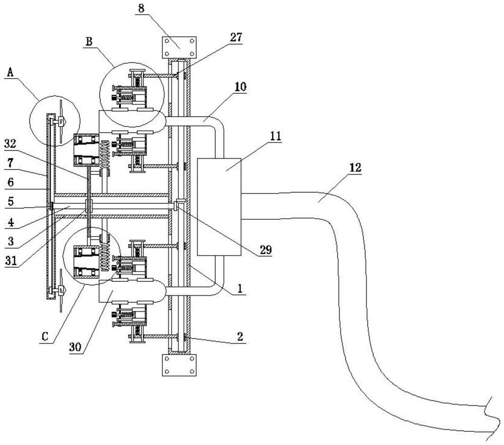
[0025]The protective structure of the exhaust branch pipe under the vehicle chassis includes a mounting pipe 1 and a shunt box 11 . The top and bottom ends of the mounting pipe 1 are fixedly connected with a mounting plate 8 , and the two mounting plates 8 are symmetrical with the center of the mounting pipe 1 . The shafts are arranged symmetricall...


PUM


Abstract

The protective structure of the exhaust branch pipe below the automobile chassis comprises a mounting pipe and a flow dividing box, the flow dividing box is located at the position, close to the top, of the right side of the mounting pipe, a connecting pipe is fixedly connected to the position, close to the center, of the left side of the mounting pipe, and a protective pipe is fixedly connected to the left end of the connecting pipe; the protective pipe and an inner cavity of the connecting pipe are communicated with each other, first bearings are fixedly connected to the positions, close to the top end and the bottom end, of the left side and the right side of the inner cavity of the protective pipe correspondingly, noise reduction is conducted on sound waves through the noise reduction pipe and the noise reduction disc, and the sound waves enter an inner cavity of the noise reduction cover through a plurality of through holes formed in the noise reduction pipe; after the noise reduction cover collides back and forth in the inner cavity of the noise reduction cover, the sound volume is reduced and then output, the noise volume of wheels during high-speed driving is greatly reduced, meanwhile, the best smoothness of an exhaust pipeline can be guaranteed during low-speed driving, the performance power of a vehicle can be better improved, and energy consumption can be better saved.

Description

technical field [0001] The invention relates to the technical field of automobile production and maintenance, in particular to a protective structure for an exhaust branch pipe under an automobile chassis. Background technique [0002] The exhaust pipe is a very important part in the car. Its patency can ensure the smooth exhaust of the vehicle, so that the fuel can be fully burned to achieve the best power value; [0003] However, when the car is driving, especially at high speed, it will generate loud noises. Driving on urban streets at night seriously affects the rest of residents. It is true that vehicles with large displacement will choose to install silencers, and when the vehicle is driving at low speeds The exhaust pipe will not discharge large exhaust gas, and the gas pressure is low. The installation of the muffler device will affect the exhaust effect of the vehicle to a certain extent when driving at low speed. Existing vehicles have long exhaust pipes and low i...

Claims


Application Information

Patent Timeline
Patent Type & Authority Applications(China)
IPC IPC(8): F01N13/18F01N13/08F01N13/00F01N1/08B60K13/04
CPCF01N13/1805F01N13/08F01N13/00F01N1/082B60K13/04Y02T10/12
Inventor 吴飞
Owner 吴飞
Why Eureka
Try Eureka