
Heat sealing mechanism on compound machine

A laminating machine and thermal laminating technology, applied in the field of laminating machines, can solve problems such as inability to continue laminating, increasing labor costs, and reducing the quality of laminated printed products, and achieve the effects of facilitating later maintenance and repair, saving manpower and time, and improving processing efficiency

Pending Publication Date: 2022-05-27
WEINAN SANLI PRINTING MACHINERY
View PDF0 Cites 0 Cited by
  • Summary
  • Abstract
  • Description
  • Claims
  • Application Information

AI Technical Summary

Problems solved by technology

[0002] Dry lamination and solvent-free lamination are two different processes. Among them, high-barrier materials use dry lamination, and their evaporation and drying can be printed at high speed; while breathable materials use solvent-free lamination without drying equipment, so the speed is relatively low. At present The problem is that when three different materials need to be compounded, the materials need to pass through the dry compound machine successively, then take out the material, and then replace it with a solvent-free compound machine, which cannot be compounded continuously. This method makes the compound surface of the material unable to keep flat Consistent, such as air bubbles, gaps, etc., will reduce the quality of the composite printed matter, and at the same time increase the labor cost virtually, and the processing efficiency of the base material is low; secondly, the two independent processes make the machine occupy a large area, and the coating lamination machine has a single function. Not conducive to later maintenance and repair

Method used


Image

  • Heat sealing mechanism on compound machine

Examples


Embodiment Construction

[0013] The following embodiments in conjunction with the accompanying drawings and specific embodiments of a heat-closing mechanism on a composite machine of the present invention are described.

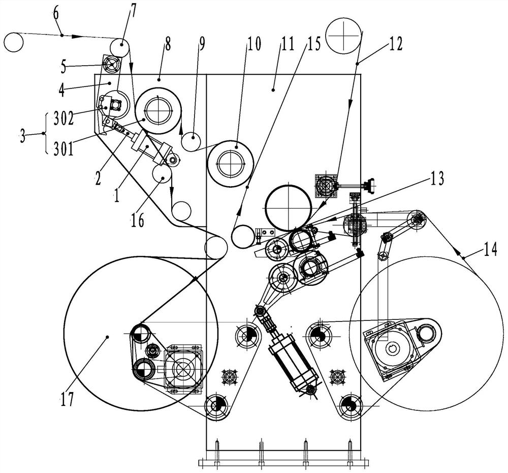
[0014] Figure 1Schematic structural diagram of the heat-closing mechanism on the composite machine of the present invention, in the drawing, the heat-sealing mechanism on the composite machine, including a wall panel 11, one end of the wall plate 11 is provided with a first thermal composite mechanism 13, the first substrate 12 and the second substrate 14 by the first thermal composite mechanism 13 after the intermediate composite substrate 15 is sent out from the cooling roller 10, the other end of the wall plate 11 is provided with an extended wall plate 8, the lengthened wall plate 8 is provided with a first guide roller 9, a second heat sealing mechanism 3 and a second guide roller 7, The second heat sealing mechanism 3 includes a second hot sealing roller 301 and a second hot seali...


PUM


Abstract

The invention provides a heat sealing mechanism on a compound machine, one end of a wallboard is provided with a first heat compounding mechanism, a first base material and a second base material are sent out from a cooling roller after passing through a middle composite base material of the first heat compounding mechanism, the other end of the wallboard is provided with a lengthened wallboard, and the lengthened wallboard is provided with a first guide roller, a second heat sealing mechanism and a second guide roller. The first guide roller is arranged on the left side of the cooling roller to supply the middle composite base material, the second heat sealing mechanism is arranged on the upper side of the first guide roller, and the second guide roller is arranged on the upper side of the second heat sealing mechanism to supply a third base material to the second heat sealing mechanism. Under the condition that the original composite structure is not changed, the composite base material can be compounded again by adding the third base material composite structure, and the finished product is wound by the winding mechanism, so that the processing efficiency of the base material is improved, the manpower and time are saved, the dry-type compounding function and the solvent-free compounding function are integrated, the occupied area is saved, and the production cost is reduced. And later maintenance and overhaul are facilitated.

Description

Technical field [0001] The present invention relates to a composite machine, specifically to a heat-closing mechanism on a composite machine. Background [0002] Dry composite and solvent-free composite is two different processes, of which the high barrier material uses dry composite, its evaporation drying can be printed at high speed; and the breathable material uses solvent-free composite, no drying equipment so the speed is low, the current problem is: when the need to composite three different materials, the material needs to be taken sequentially through the dry laminating machine, and then replaced by a solvent-free laminating machine, can not be continuously composited, this way so that the composite surface of the material can not be kept flat and consistent, such as bubbles, gaps, etc., The quality of composite prints is reduced, while invisibly increasing labor costs, the processing efficiency of the substrate is low; secondly, the two independent processes make the ma...

Claims


Application Information

Patent Timeline
Patent Type & Authority Applications(China)
IPC IPC(8): B32B37/06B32B37/08B65H23/26
CPCB32B37/06B32B37/08B65H23/26Y02P70/50
Inventor 李丁
Owner WEINAN SANLI PRINTING MACHINERY
Learn More