
Hanging feeding device and method for powder materials

A feeding device and powder material technology, which is applied in the direction of traveling mechanism, transportation and packaging, loading/unloading, etc., can solve problems such as the impact on workers' health, and achieve the effects of avoiding operational hazards, improving production efficiency, and improving safety

Pending Publication Date: 2022-05-27
SAILUN GRP CO LTD
View PDF0 Cites 0 Cited by
  • Summary
  • Abstract
  • Description
  • Claims
  • Application Information

AI Technical Summary

Problems solved by technology

[0003] In the process of feeding, most of the material bags have their own angle of repose, and the materials cannot fall completely by their own gravity, and workers need to shake the material bags to make the materials fall. influences

Method used


Image

  • Hanging feeding device and method for powder materials
  • Hanging feeding device and method for powder materials

Examples


Embodiment 1

[0045] The powder material hoisting device of the present invention is used for feeding, and the specific process of feeding is as follows:

[0046] S1: Select the appropriate height and position to install the longitudinal rail 1;

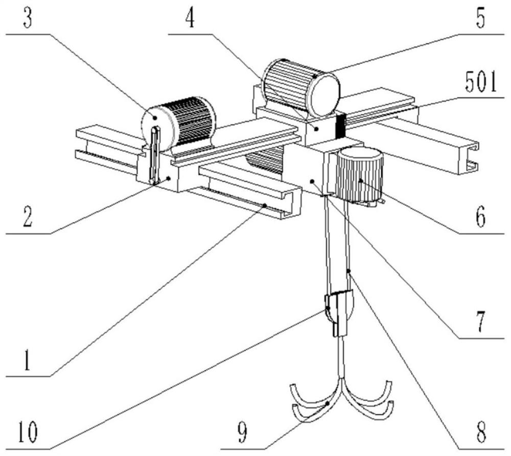
[0047]S2: The controller 501 controls the longitudinal movement motor 3 and the lateral movement motor 5 to drive the lateral movement base 4 to move above the material bag;

[0048] S3: Control the rotation of the crimping motor 12 by the controller 501 to lower the wire rope 8 to a suitable height, and hang the material bag on the hook 9;

[0049] S4: control the curling motor 12, the longitudinal movement motor 3 and the transverse movement motor 5 through the controller 501 to transport the material bag to the feeding port for feeding;

[0050] S5: The weight sensor collects the gravity value of the material bag in real time and transmits it to the controller 501;

[0051] S6: The controller 501 sets thresholds for starting and stopping the ...

Embodiment 2

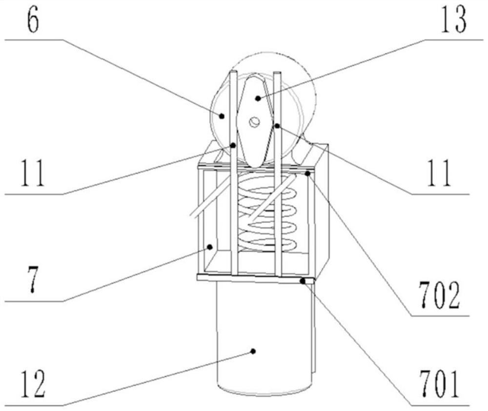
[0058] In this embodiment, the cam is set with rounded corners, in order to realize the close contact between the cam and the sliding rod, and improve the stability of the reciprocating motion of the sliding rod. The length ratio between the maximum and minimum cam widths is usually not less than 1.2:1, preferably 2.5:1. The vibration amplitude of the hook can be adjusted by adjusting the length ratio between the maximum and minimum cam widths. The faster the wire rope falls, the greater the vibration amplitude, which is more conducive to overcoming the angle of repose of the material bag.

[0059] In addition, in this embodiment, the cam is arranged in a symmetrical structure, and the hook vibrates up and down once every 180 degrees of rotation of the cam.

[0060] The entire vibration feeding process can be controlled remotely by the controller, and workers do not need to approach the material bag, which avoids dust damage and improves production efficiency.


PUM


Abstract

The invention relates to the technical field of tire production, and provides a powder material crane feeding device which comprises a box body, the winding drum is arranged in the box body and is wound with a steel wire rope; the vibration motor is mounted on the box body; the cam is connected with the output end of the vibration motor; rotation of the cam can drive the sliding rod to reciprocate in the vertical direction of the steel wire rope, so that the steel wire rope continuously completes the alternate action of restoring to the original shape after opening the angle, and vibration feeding of the hung materials is achieved. In the whole process, a worker can remotely control the crane to move, when materials are thrown, after the weight of a hoisted material bag is smaller than a set numerical value, a vibration motor drives a cam to do reciprocating motion, during the period, a lifting hook repeatedly does slow-rising and fast-falling motion, the material bag continuously vibrates, the repose angle of powder is damaged, and the powder continuously falls down; the operation danger caused by manual shaking of the crane and the risk that powder drifts away and is sucked in are avoided, and the safety is improved.

Description

technical field [0001] The invention relates to the field of tire production, in particular to a special crane with a vibrating device, which is specifically applied to the delivery of bagged powder in a tire manufacturing banburying project. Background technique [0002] Mixing engineering is the first process in the tire manufacturing process and plays a vital role in tire performance. The basic working principle of the banburying process is: the process of banburying rubber and various compounding agents into the rubber material required for the next process according to the formula. Powder materials such as carbon black and zinc oxide are usually bagged materials, which are transported to the feeding port by using a hoist. Through the opening at the bottom of the bag, the materials fall into the feeding port under the action of gravity and then are transported. [0003] During the feeding process, most of the material bags have an angle of repose, and the material canno...

Claims


Application Information

Patent Timeline
Patent Type & Authority Applications(China)
IPC IPC(8): B66C17/26B66C11/16B66C9/14B66C13/16B66C13/22B66C13/40B65G65/44
CPCB66C17/26B66C11/16B66C9/14B66C13/16B66C13/22B66C13/40B65G65/44B65G65/005B65G2203/042B65G2203/0258Y02P10/25
Inventor 王中医孙洪超杨丹丹孙杰于悦苑伍德胡立皓陈志远
Owner SAILUN GRP CO LTD
Learn More