Gas pipeline under-pressure leaking stoppage device and leaking stoppage method thereof

A technology for plugging leaks under pressure and gas pipelines, applied in valve devices, container filling methods, container discharge methods, etc., can solve problems such as affecting people's normal life, wasting gas resources, and natural gas leakage, avoiding environmental pollution and reducing environmental pollution. Personal safety hazards, good blocking effect, and the effect of preventing gas leakage

Active Publication Date: 2022-05-27
潍坊华润燃气有限公司
View PDF12 Cites 0 Cited by
  • Summary
  • Abstract
  • Description
  • Claims
  • Application Information

AI Technical Summary

Problems solved by technology

Although the buried laying can protect the pipeline and does not affect agricultural cultivation and human activities on the ground, there are still the following problems: the pipeline laid underground is due to natural reasons such as natural corrosion of the pipeline, chemical corrosion, or drilling, drilling, piling, etc. Such as human-made reasons, resulting in large or small cracks and holes in the buried gas pipelines, these cracks and holes lead to natural gas leakage
When using the above method for construction, it is necessary to exhaust the gas in the gas pipeline first, which takes a long time. In addition, the natural gas in the gas pipeline is discharged into the atmosphere, which not only wastes gas resources, but also pollutes the environment, seriously affecting people's normal life. Life

Method used


Image

  • Gas pipeline under-pressure leaking stoppage device and leaking stoppage method thereof
  • Gas pipeline under-pressure leaking stoppage device and leaking stoppage method thereof
  • Gas pipeline under-pressure leaking stoppage device and leaking stoppage method thereof

Examples


specific Embodiment approach

[0050] It should be noted that the structures, proportions, sizes, etc. shown in the accompanying drawings in this specification are only used to cooperate with the contents disclosed in the specification, so as to be understood and read by those who are familiar with the technology, and are not used to limit the implementation of the present invention. Any modification of the structure, the change of the proportional relationship or the adjustment of the size, without affecting the effect that the present invention can produce and the purpose that can be achieved, should fall within the scope of the technical content disclosed in the present invention. within the range.

[0051] At the same time, the terms such as "up", "down", "left", "right", "middle" and "one" quoted in this specification are only for the convenience of description and clarity, and are not used to limit this specification. The implementable scope of the invention, and the change or adjustment of the relati...

Embodiment 1

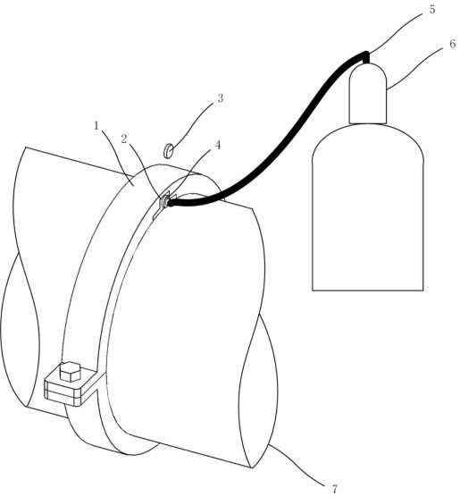
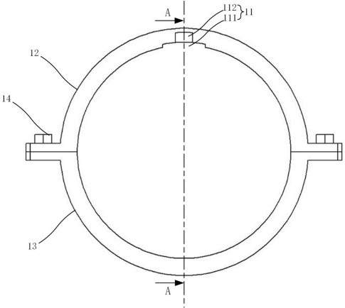
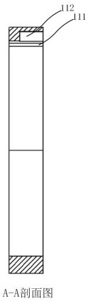
[0053] combined with Figures 1 to 5 , this embodiment provides a leakage plugging device under pressure for a gas pipeline, which includes a clamp 1 and a leakage plugging mechanism 2. The inner ring surface of the clamp 1 is axially provided with a first groove 11. The leakage plugging mechanism 2 can be tightly inserted into the first groove 11. The leakage blocking mechanism 2 includes a leakage blocking body 21 with the same curvature and the same material as the pipeline 7. The bottom of the leakage blocking body 21 is vertically provided with an air inlet 22. A cylindrical air passage 23 that communicates with the air inlet 22 is horizontally provided, and a one-way valve assembly 24 for blocking the air passage 23 is axially provided in the air passage 23, and the one-way valve assembly 24 is sealed and connected A sealing cover 3 or a connecting head 4 , one end of the connecting head 4 can be inserted into and open the one-way valve assembly 24 to communicate with th...

Embodiment 2

[0062] combined with Figures 6 to 17 , this embodiment provides a one-way valve assembly 24 suitable for Embodiment 1, and the specific technical solution is as follows:

[0063] like Image 6 and Figure 7 As shown, the one-way valve assembly 24 includes a one-way valve body 241, such as Figure 8 As shown, the one-way valve body 241 is provided with a cavity 2411 which communicates with the air passage 23. The cavity 2411 is provided with a valve seat 242 and a valve core 243, and the valve core 243 is connected to the core rod 244. The core rod 244 is symmetrically provided with two limit slide rods 2441 perpendicular to the core rod 244 , and the inner wall of the one-way valve body 241 is axially provided with a limit rod corresponding to the limit slide rod 2441 . The position slide groove 2412 and the spring 245 are arranged between the end of the one-way valve body 241 away from the valve seat 242 and the limit slide rod 2441, and the valve core 243 and the core ro...


PUM


Abstract

The invention relates to the technical field of gas pipeline repairing, in particular to a gas pipeline under-pressure leaking stoppage device and a leaking stoppage method thereof. The gas pipeline under-pressure leaking stoppage device comprises a hoop and a leaking stoppage mechanism, a first groove is axially formed in the inner ring face of the hoop, the leaking stoppage mechanism can be tightly inserted into the first groove, the leaking stoppage mechanism comprises a leaking stoppage body which is the same as a pipeline in curvature and material, an air inlet hole is vertically formed in the bottom of the leaking stoppage body, and a cylindrical air channel communicated with the air inlet hole is horizontally formed in the leaking stoppage body. The one-way valve assembly is connected with the sealing cover or the connector in a sealing mode, one end of the connector can be inserted into and open the one-way valve assembly to be communicated with the air channel, and the other end of the connector is communicated with the air storage tank through a hose. The construction efficiency is high, the plugging effect is good, pressure can be relieved in time in the under-pressure plugging process, leaked gas can be collected, the labor intensity of workers is relieved, and energy recycling is achieved.

Description

technical field [0001] The invention relates to the technical field of gas pipeline repair, in particular to a gas pipeline leakage plugging device under pressure and a leakage plugging method thereof. Background technique [0002] Gas pipelines are generally steel natural gas pipelines, which refer to pipelines that transport natural gas (including associated gas generated from oil fields) from mining sites or processing plants to urban gas distribution centers or industrial enterprise users, also known as gas pipelines. In order to operate safely, gas pipelines are usually not allowed to be laid overhead, and are generally laid underground. Although buried laying can protect the pipeline and does not affect agricultural cultivation and human activities on the ground, there are still the following problems: the pipelines laid underground are due to natural causes such as natural corrosion and chemical corrosion of the pipeline, or drilling, drilling, and piling. Due to man...

Claims


Application Information

Patent Timeline
Patent Type & Authority Applications(China)
IPC IPC(8): F16L55/168F16L55/172F17C5/06F17C13/04F16K15/06
CPCF16L55/168F16L55/172F17C5/06F17C13/04F16K15/063F17C2221/033F17C2223/0123F17C2260/046F17C2260/044
Inventor 张正超王春光王红利赵晓涛刘善航武军杰赵国胜
Owner 潍坊华润燃气有限公司
Why Eureka
Try Eureka