A Planar Lumberg Lens Antenna Based on Sparse Phased Array Feeding

A technology of Lunberg lens antenna and plane lens, which is applied in the directions of antenna arrays, antennas, and antenna arrays that are energized separately, can solve the problems of high cost, decreased radiation power, and restrict the use of ultra-high-gain wireless communication scenarios. Processing cost, quantity reduction, effect of reducing antenna profile height

A technology of Lunberg lens antenna and plane lens, which is applied in the directions of antenna arrays, antennas, and antenna arrays that are energized separately, can solve the problems of high cost, decreased radiation power, and restrict the use of ultra-high-gain wireless communication scenarios. Processing cost, quantity reduction, effect of reducing antenna profile height

CN114552227BActive Publication Date: 2022-07-26UNIV OF ELECTRONICS SCI & TECH OF CHINA

Image

  • A Planar Lumberg Lens Antenna Based on Sparse Phased Array Feeding
  • A Planar Lumberg Lens Antenna Based on Sparse Phased Array Feeding
  • A Planar Lumberg Lens Antenna Based on Sparse Phased Array Feeding

Examples


Embodiment 1

[0049] A planar Lumberg lens antenna based on sparse phased array feeding is designed and obtained according to the following steps:

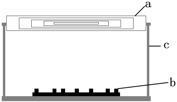
[0050] Step 1. According to the indicator, the 10 dB beam width of the feed antenna is 34°, and the spherical Lunberg lens antenna is designed through electromagnetic simulation software. Specifically, in this embodiment, a spherical Lunberg lens composed of 5 layers of dielectric materials is first designed. Antenna, the relative permittivity of the innermost dielectric material of the spherical Lunberg lens antenna is 2, and the relative permittivity decreases at equal intervals from the inside to the outside, and the electrical parameter of the outermost material is 1; and the spherical Lunberg lens antenna The radius R;

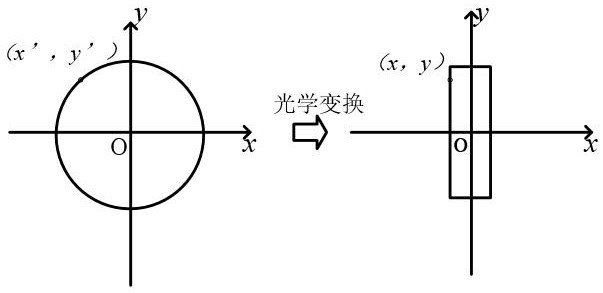
[0051] Step 2. Use optical transformation to compress the spherical Lumberg lens antenna obtained in step 1 into a cylindrical plane lens. The specific process is:

[0052] In the Cartesian coordinate system, the spherica...


PUM


Abstract

The purpose of the present invention is to provide a plane Lunberg lens antenna based on sparse phased array feeding, which belongs to the technical field of antennas. The antenna compresses the spherical Lumberg lens antenna into a plane structure through optical transformation, and then uses an optimization algorithm to optimize a large-spacing sparse feed array that matches the plane lens structure. The excitation amplitude does not change under different scanning angles to ensure the EIRP index within the scanning range; at the same time, the antenna also has the advantages of high gain, low profile and low cost, which has strong engineering practicability.

Description

technical field [0001] The invention belongs to the technical field of antennas, and in particular relates to a plane Lumberg lens antenna based on sparse phased array feeding. Background technique [0002] With the rapid development of wireless communication technologies such as 5G and low-orbit satellite communication, the application scenarios of wireless communication are becoming more and more complex. As an important device in a wireless communication system, the performance requirements of the antenna are becoming higher and higher. In wireless communication scenarios such as 5G and low-orbit satellite communication, there are practical applications such as long-distance communication, beam alignment, and small space assembly. Therefore, antennas are required to have high gain, fast beam switching, and low profile requirements. [0003] Phased array antennas are the most widely used beam scanning antennas in communication systems. They have the capabilities of fast w...

Claims


Application Information

Patent Timeline
26 Jul 2022
Publication
CN114552227B
IPC
H01Q15/08; H01Q19/06; H01Q1/12; H01Q21/06
CPC
H01Q15/08; H01Q19/06; H01Q1/12; H01Q21/061; Y02D30/70
Inventors
郑斌; 程钰间