
Copper foil cutting device

A cutting and copper foil technology, used in transportation and packaging, thin material processing, metal processing, etc., can solve problems such as uneven cutting surface, shaking of electrolytic copper foil, and wrinkling of cut products

Pending Publication Date: 2022-05-31
GUANGDONG FINE YUAN SCI TECH CO LTD
View PDF7 Cites 1 Cited by
  • Summary
  • Abstract
  • Description
  • Claims
  • Application Information

AI Technical Summary

Problems solved by technology

In the rapid development of today's electronic information industry, electrolytic copper foil is called the "neural network" of electronic product signal and power transmission and communication. The device cuts and collects in sections. The existing slitting device cuts directly with a cutter after its transmission guide roller is transferred to the cutting platform. However, the electrolytic copper foil shakes during the cutting process, and at the same time, there is no Flattening, so the cutting surface is uneven, the finished product is wrinkled, and the collection of the finished product is mainly dependent on manual work, and the work efficiency is low

Method used


Image

  • Copper foil cutting device
  • Copper foil cutting device
  • Copper foil cutting device

Examples


Embodiment Construction

[0026] The technical solutions in the embodiments of the present invention will be clearly and completely described below with reference to the accompanying drawings in the embodiments of the present invention. Obviously, the described embodiments are only a part of the embodiments of the present invention, but not all of the embodiments. Based on the embodiments of the present invention, all other embodiments obtained by those of ordinary skill in the art without creative efforts shall fall within the protection scope of the present invention.

[0027] In order to make the above objects, features and advantages of the present invention more clearly understood, the present invention will be described in further detail below with reference to the accompanying drawings and specific embodiments.

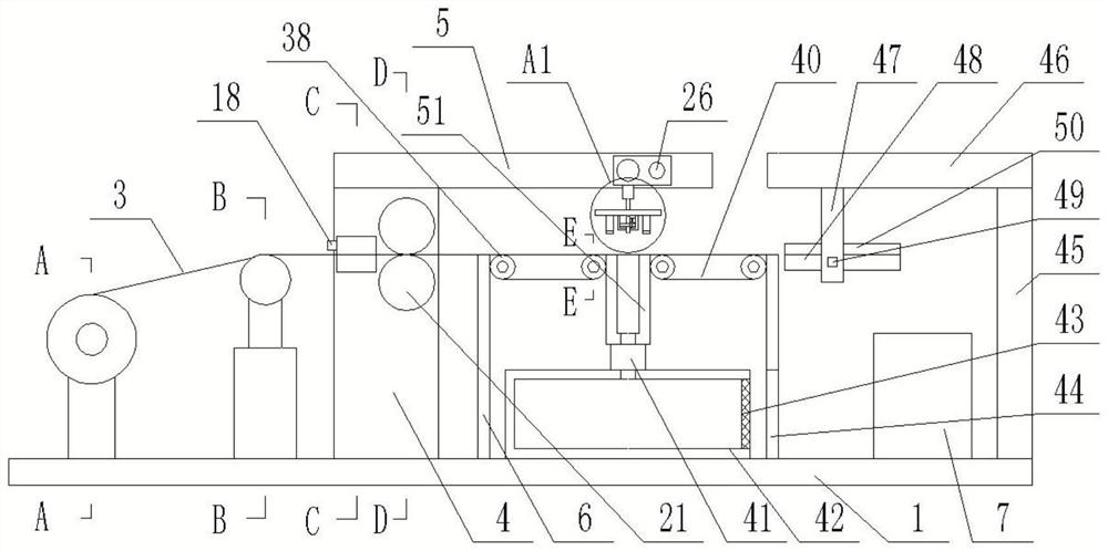
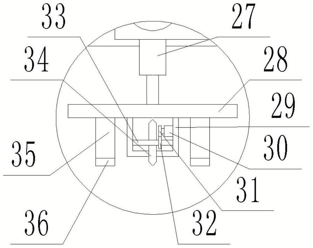
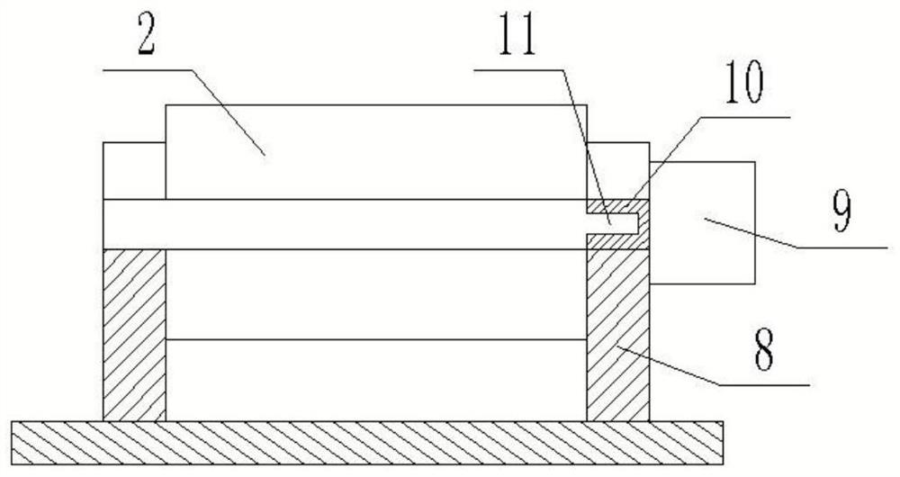
[0028] refer to Figure 1-8The invention provides a copper foil cutting device, comprising: a bottom plate 1, a discharge mechanism is provided on one side of the top surface of the bot...


PUM


Abstract

The invention discloses a copper foil cutting device which comprises a bottom plate, a discharging mechanism is arranged on one side of the top face of the bottom plate, a discharging roller is detachably connected to the top of the discharging mechanism, electrolytic copper foil is wound on the outer wall of the discharging roller, a tensioning mechanism is arranged on the side, located on the discharging mechanism, of the top face of the bottom plate, and supporting plates are fixedly connected to the two sides of the middle of the top face of the bottom plate correspondingly. A paving mechanism and a transmission mechanism are arranged between the two supporting plates, a moving mechanism is arranged between the two cross beams, a cutting mechanism is arranged at the bottom of the moving mechanism, a conveying shell is arranged below the cutting mechanism, the bottom face of the conveying shell is fixedly connected with the top face of the bottom plate, and conveying mechanisms are arranged on the two sides of the top face of the conveying shell correspondingly. A dust collection mechanism is arranged between the two conveying mechanisms, a material taking mechanism is arranged on the other side of the top face of the bottom plate, a material collecting box is arranged below the material taking mechanism, and the electrolytic copper foil wound on the discharging roller sequentially penetrates through the tensioning mechanism, the paving mechanism, the transmission mechanism and the cutting mechanism to be cut together with the dust collection mechanism.

Description

technical field [0001] The invention relates to the field of electrolytic copper foil production technology, in particular to a copper foil cutting device. Background technique [0002] CCL is the basic material of the electronics industry. In order to meet the needs of manufacturing copper clad laminates, electronic grade copper foils (purity 99.7% or more, thickness 5um-105um) are often cut into sheets. Electrolytic copper foils are copper clad laminates (CCL) and printed circuit boards (PCBs), lithium Important material for the manufacture of ion batteries. In the rapid development of today's electronic information industry, electrolytic copper foil is called the "neural network" of signal and power transmission and communication of electronic products. The electrolytic copper foil slitting device is located after the rewinding device, and is transmitted to the slitting after the rewinding process. The device performs segmented cutting and collection. The existing slitt...

Claims


Application Information

Patent Timeline
IPC IPC(8): B26D1/12B26D7/32B26D7/18B26D7/14B26D7/08B26D7/00B65H19/12
CPCB26D1/125B26D7/32B26D7/18B26D7/1863B26D7/325B26D7/14B26D7/08B26D7/00B65H19/12B26D2007/322Y02E60/10
Inventor 沈福辉李洪波罗志宏叶铭谢伟成谢元荣
Owner GUANGDONG FINE YUAN SCI TECH CO LTD
Learn More