Active induced cracking device suitable for continuous reinforced concrete pavement

A technology of reinforced concrete and concrete layers, applied to cohesive pavement, roads, roads and other directions paved on site, can solve the problems of affecting the aesthetics of the road surface, driving comfort, affecting the aesthetics and traffic, and increasing construction costs, etc., to achieve Improve the comfort of driving, improve the aesthetics, and enhance the effect of road surface strength

Pending Publication Date: 2022-05-31
CHINA ROAD & BRIDGE
0 Cites 0 Cited by

AI-Extracted Technical Summary

Problems solved by technology

Moreover, the location where cracks occur is a weak load area, and uncontrollable cracks will gradually widen or break under heavy traffic, affecting aesthetics and traffic
[0003] A common way to solve the above problems in the field of construction is to set saw marks on the road surface. This saw mark is generally set when the concrete is solidified enough for workers to operate. However, the width of the saw marks is wide. In order to make the road surface If it is relat...

Method used

Improve the bonding to base 2 and road surface by setting the first bituminous concrete layer 6, the first geocell layer 7, the second bituminous concrete layer 8, the second geocell layer 9 and the third bituminous concrete layer 10 In addition to the strength, the set first geocell layer 7 and the second geocell layer 9 can enhance the bearing capacity.
The bonding layer that is provided with can realize the connection to graphene concrete layer 3 and base layer 2, enhances bonding strength, avoids delamination, by setting continuous longitudinal welding main reinforcement 4, can seam cement concrete pavement due to setting transverse expansion joint , various road surface diseases caused by shrinkage joints, and also improve the performance of the pavement. Setting up the vertical ribs 5 can fix the main ribs 4 and play a supporting role. The distance between the main ribs 4 is 20-25cm. The spacing of the vertical ribs 5 set is 0.8-1.2m; by adding graphene into the graphene concrete layer 3, the thermal conductivity can be improved, so that the top of the board and the inside of the board can be kept at the same temperature during heating and cooling, and the temperature can be raised and lowered synchronously , so that the graphene concrete layer 3 can be slightly deformed, the cracks are more uniform and small, and the overall road surface strength is enhanced, and the graphene concrete layer 3 can be realized by the inducer arranged at the bottom of the erection bar 5 The active cracking can control the cracking, and the graphene concrete layer 3 can be cracked uniformly by setting the force-bearing weak area on the inducer, so as to improve the aesthetics of the road surface and the driving comfort.
The moisture that enters from crack can enter in the arc-shaped cavity 15 by water guide hole 17, by the lower water guide protrusion 16 of two ends, water is poured in the soil layer on foundation groove 1 both sides, Prevent water from entering the base layer 2, so as to play a waterproof effect.
The positioning plate 13...

Abstract

The active induced cracking device comprises a foundation trench formed in the top face of a soil layer, a base layer is arranged on the bottom face of the foundation trench, a bonding layer is arranged on the top face of the base layer, a graphene concrete layer is arranged on the top face of the bonding layer, and the graphene concrete layer is arranged on the top face of the graphene concrete layer. A plurality of main reinforcements are laid on the top in the graphene concrete layer in the transverse direction of the pavement at equal intervals, a plurality of erection reinforcements are laid below the main reinforcements in the longitudinal direction of the pavement at equal intervals, and the crossed positions of the erection reinforcements and the main reinforcements are bound through steel wires; a plurality of induction parts are laid at equal intervals below the plurality of erection ribs in the longitudinal direction of the road surface, a plurality of heat conduction parts are welded at equal intervals on the bottom surfaces of the induction parts, the bottoms of the heat conduction parts penetrate through the bonding layer and then are located in the base layer, and the tops of the heat conduction parts are located in the graphene concrete layer.

Application Domain

Paving reinforcementsIn situ pavings +1

Technology Topic

Reinforced concreteGeotechnical engineering +3

Image

  • Active induced cracking device suitable for continuous reinforced concrete pavement
  • Active induced cracking device suitable for continuous reinforced concrete pavement
  • Active induced cracking device suitable for continuous reinforced concrete pavement

Examples

  • Experimental program(1)

Example Embodiment

[0023] The following will be combined with the accompanying drawings in the embodiments of the present invention, the technical solution in the embodiments of the present invention will be described clearly and completely, it is clear that the embodiments described are only a part of the embodiment of the present invention, not all embodiments. Based on embodiments in the present invention, all other embodiments obtained by those of ordinary skill in the art without making creative work, are within the scope of protection of the present invention.
[0024] In order to make the above-described objects, features and advantages of the present invention can be more obvious and understandable, the following in conjunction with the accompanying drawings and specific embodiments of the present invention will be further detailed description.
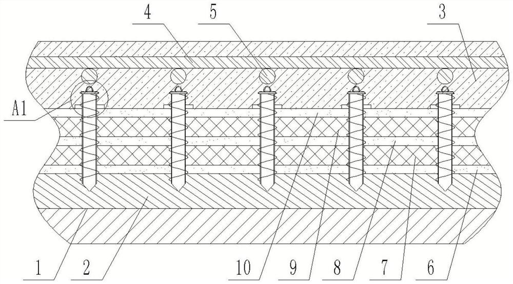
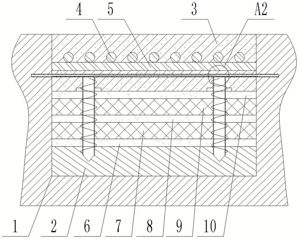
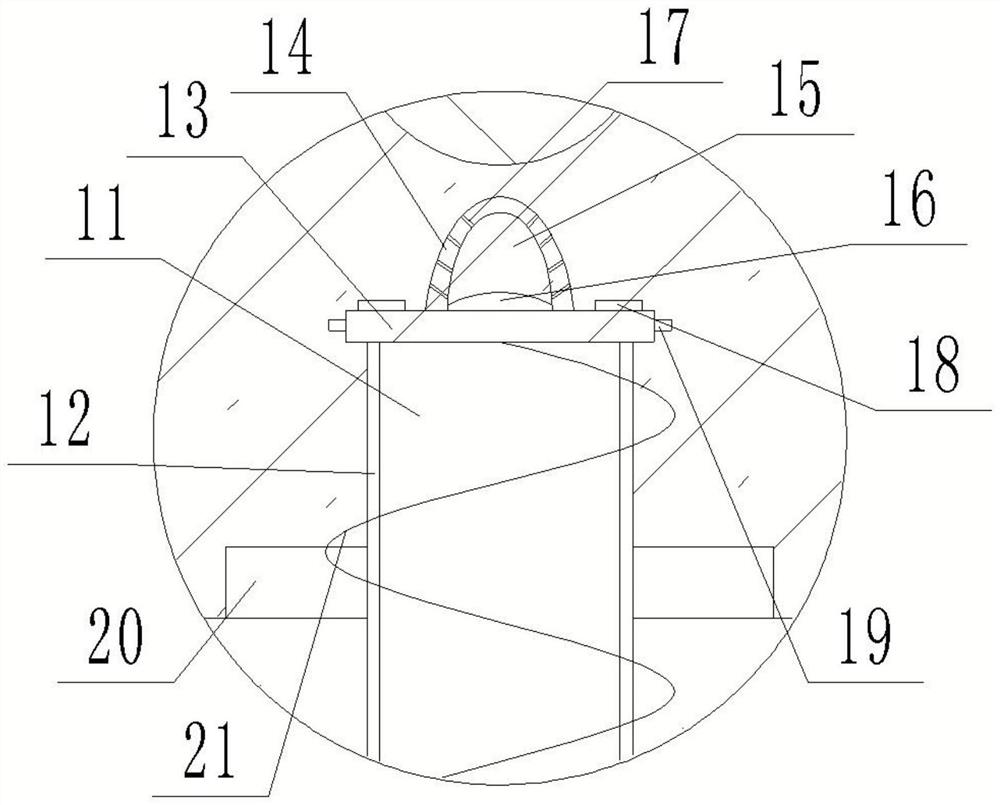
[0025] Reference Figure 1-4 , the present invention provides an active induction cracking apparatus suitable for continuous reinforced concrete pavement, comprising: a base groove 1 opened on the top surface of the soil layer, the base groove 1 bottom surface is provided with a base layer 2, the top surface of the base layer 2 is provided with a bonding layer, the top surface of the adhesive layer is provided with a graphene concrete layer 3, the top of the graphene concrete layer 3 is laid along the transverse direction of the pavement with a number of main ribs 4, a number of main ribs 4 below the road surface along the longitudinal direction of the road surface equal spacing laying a number of frame ribs 5, Several frame ribs 5 and a number of main ribs 4 cross position through the wire binding, a number of frame ribs 5 below along the road longitudinal direction of equal spacing laying a number of induction parts, the bottom surface of the induction parts equal spacing welding a number of heat transfer parts, the bottom of the heat conductive parts through the adhesive layer is located in the base layer 2, the top of the heat conductive parts is located in the graphene concrete layer 3.
[0026] The set of adhesive layer can realize the connection of graphene concrete layer 3 and base layer 2, enhance the bonding strength, avoid layering, by setting up continuous longitudinal welding of the main rib 4, you can seam cement concrete pavement due to the setting of transverse expansion joints, shrink joints caused by various road surface diseases, but also improve the performance of pavement use, set the erection rib 5 can play a supporting role on the main rib 4 fixed effect, the spacing between the main ribs set 4 is 20-25cm, The spacing of the set rib 5 is 0.8-1.2m; by adding graphene to the graphene concrete layer 3, the thermal conductivity can be improved, so that the temperature of the top of the plate and the plate is maintained consistent during heating and cooling, and the temperature is synchronized and cooled, so that the graphene concrete layer 3 can produce less deformation, make the crack crack more uniform and fine, enhance the overall pavement strength, and the active cracking of the graphene concrete layer 3 can be controlled by the active cracking of the graphene concrete layer 3 set at the bottom of the frame reinforcement 5, and the graphene concrete layer 3 can be evenly distributed cracking by setting the weak area of the force on the inducer , improve the aesthetics of the road surface and the comfort of driving.
[0027]Further optimizing the scheme, the adhesive layer comprises a first asphalt concrete layer 6, the bottom surface of the first asphalt concrete layer 6 is fixed with the base layer 2 top surface, the top surface of the first asphalt concrete layer 6 is fixed with the first geogrid room layer 7, the top surface of the first geogrid room layer 7 is connected to the second asphalt concrete layer 8, the top surface of the second asphalt concrete layer 8 is fixed with a second geogrid room layer 9, and the top surface of the second geogrid room layer 9 is fixed with a third asphalt concrete layer 10, The top surface of the third asphalt concrete layer 10 is fixed with the bottom surface of the graphene concrete layer 3, and the heat conductive part runs through the first asphalt concrete layer 6, the first geolattice room layer 7, the second asphalt concrete layer 8, the second geolattice chamber layer 9 and the third asphalt concrete layer 10.
[0028] By providing the first asphalt concrete layer 6, the first geolattices room layer 7, the second asphalt concrete layer 8, the second geolattice chamber layer 9 and the third asphalt concrete layer 10 to improve the bonding strength of the base layer 2 and the road surface, the first geolattices chamber layer 7 and the second geolattices chamber layer 9 can enhance the load-bearing capacity.
[0029] To further optimize the scheme, the thermal conductive parts include a thermal conductive column 11, the thermal conductive column 11 is set to a steel material, the thermal conductive column 11 is fixed to the thermal conductive layer 12 on the outer wall, the thermal conductive layer 12 is set to a copper material, the bottom surface of the thermal conductive column 11 is set to a tapered structure, the bottom of the thermal conductive column 11 is set within the base layer 2, and the top surface of the thermal conductive column 11 is welded to the bottom surface of the inducer.
[0030] The thermal conductive column 11 can play a thermal conductive effect, so that the temperature of the base layer 2 upper layer, the adhesive layer and the graphene concrete layer 3 is balanced, so as to avoid the phenomenon of local heat unevenness, while the thermal conductive column 11 can be set to the steel material can improve the overall strength at the same time, can play a fixed effect on the adhesive layer, enhance the bonding layer and the base layer 2 and the road surface connection strength, but also play an auxiliary thermal conductivity effect, set the thermal conductive layer 12 can use the copper material itself strong thermal conductivity performance, improve the thermal conductivity.
[0031] Further optimizing the scheme, the first asphalt concrete layer 6, the second asphalt concrete layer 8 and the third asphalt concrete layer 10 are embedded in each other within the first geolattices room layer 7 and the second geocertics chamber layer 9 to make it a whole.
[0032] Further optimize the scheme, the induction member comprises a positioning plate 13, the positioning plate 13 is provided with a bar structure, the bottom surface of the positioning plate 13 is welded with the top surface of the thermal conductive column 11, the two ends of the positioning plate 13 are located in the soil layer on both sides of the base groove 1, the positioning plate 13 is fixed with a bar column 14, the top surface of the bar column 14 is set to an arc structure, the bar column 14 is provided with an arc cavity 15, the positioning plate 13 is provided with waterproof components on both sides, and the curved cavity 15 is provided with a water-conducting component.
[0033]The positioning plate 13 can be set up to assist the installation of the bar column 14 to play an auxiliary fixing effect, enhance stability, avoid displacement when pouring concrete, affect the location of the crack in the pavement, set the bar column 14 for the arc structure, at the top of the bar column 14 formed a weak area of the pavement force, to achieve automatic cracking, so that the pavement produces a smaller width, more uniform cracks, the set of arc cavity 15 can further make the concrete pavement produce better stress release, improve the cracking effect. The bottom surface of the positioning plate 13 is welded with the top surface of the thermal conductive column 11, making it a whole can further improve the overall connection strength.
[0034] Further optimized scheme, the water diversion component comprises a water guide convex 16, a water guide convex 16 fixed in the arc cavity 15 bottom surface, the water guide convex 16 height from the middle to the two ends of the sequential reduction, the arc cavity 15 ends and the base trough 1 on both sides of the soil layer connected, the arc cavity 15 on the inner wall of the opening of a number of water guide holes 17.
[0035] The water entering from the crack may enter the arc cavity 15 through the water diversion hole 17, through the lower water conduction bulge 16 at both ends, the water is poured into the soil layer on both sides of the base trough 1, to avoid water entering the base layer 2, playing a waterproof effect.
[0036] Further optimized solution, waterproof components include rubber strip 18, rubber strip 18 of the top surface and the positioning plate 13 top surface fixed, positioning plate 13 side fixed partition 19, rubber strip 18 and partition plate 19 are connected to the graphene concrete layer 3.
[0037] The partition plate 19 and the rubber strip 18 may play a waterproof effect, and the effect of blocking moisture can be played.
[0038] Further optimized, the thermal conductive layer 12 is fixed to the top outer wall of the contact ring 20, the bottom surface of the resistance ring 20 is connected to the top surface of the third asphalt concrete layer 10.
[0039] The contact ring 20 is provided may make the adhesive layer in full contact with the base layer 2, which has the effect of compaction.
[0040] To further optimize the scheme, the thermal conductive layer 12 is fixed on the outer wall of the spiral vane 21.
[0041] Increasing the spiral blade 21 can not only facilitate the drilling of the heat conductive parts, but also increase the contact area and improve the thermal conductivity effect.
[0042] To further optimize the scheme, graphene concrete layer 3 consists of a concrete layer, steel fibers and graphene materials.
[0043] By adding steel fibers to the graphene concrete layer 3, the toughness of the graphene concrete layer 3 can be increased and the crack size can be reduced.
[0044]In the description of the present invention, it is to be understood that the term "longitudinal", "transverse", "up", "down", "front", "back", "left", "right", "vertical", "horizontal", "top", "bottom", "inside", "outside" and other indicated orientation or position relationship is based on the orientation or position relationship shown in the drawings, only to facilitate the description of the present invention, and not to indicate or imply that the device or element referred to must have a particular orientation, structured and operated in a particular orientation, It can therefore not be construed as a limitation of the present invention.
[0045] The above-described embodiments are only a description of the preferred method of the present invention, not to limit the scope of the present invention, without departing from the spirit of the design of the present invention, the various deformations and improvements made by those of ordinary skill in the art of the technical solution of the present invention, should fall within the scope of protection determined by the claims of the present invention.

PUM

no PUM

Description & Claims & Application Information

We can also present the details of the Description, Claims and Application information to help users get a comprehensive understanding of the technical details of the patent, such as background art, summary of invention, brief description of drawings, description of embodiments, and other original content. On the other hand, users can also determine the specific scope of protection of the technology through the list of claims; as well as understand the changes in the life cycle of the technology with the presentation of the patent timeline. Login to view more.

Similar technology patents

Node and a Method for use in a Wireless Communications System

ActiveUS20100279602A1improve performance
Owner:TELEFON AB LM ERICSSON (PUBL)

Neural network module for data mining

ActiveUS7069256B1improve performancegood integration
Owner:ORACLE INT CORP

Data transmission method for use in mobile communication systems

InactiveUS20120163311A1improve performancereduce signal overhead
Owner:ELECTRONICS & TELECOMM RES INST

Classification and recommendation of technical efficacy words

Why Eureka
Try Eureka