
Rapid calculation method for sensitivity of PCB Rogowski coil current sensor

A technology of current sensor and Rogowski coil, which is applied in the direction of only measuring current, measuring current/voltage, instruments, etc., can solve the problems of PCB Rogowski coil simulation difficulties, etc., and achieve the effect of easy programming for calculation, high calculation accuracy and convenient calculation

Pending Publication Date: 2022-05-31
WUHAN UNIV
View PDF0 Cites 0 Cited by
  • Summary
  • Abstract
  • Description
  • Claims
  • Application Information

AI Technical Summary

Problems solved by technology

It is difficult to use electromagnetic simulation software to simulate PCB Rogowski coils with irregular skeletons and dense wire turns.

Method used


Image

  • Rapid calculation method for sensitivity of PCB Rogowski coil current sensor
  • Rapid calculation method for sensitivity of PCB Rogowski coil current sensor
  • Rapid calculation method for sensitivity of PCB Rogowski coil current sensor

Examples


Embodiment Construction

[0046] In order to make the object, technical solution and advantages of the present invention clearer, the present invention will be further described in detail below in conjunction with the accompanying drawings and embodiments. It should be understood that the specific embodiments described here are only used to explain the present invention, not to limit the present invention.

[0047] In the embodiment of the present invention, a common PCB Rogowski coil with thin wire turns and a complex structure with high turn density is selected for illustration.

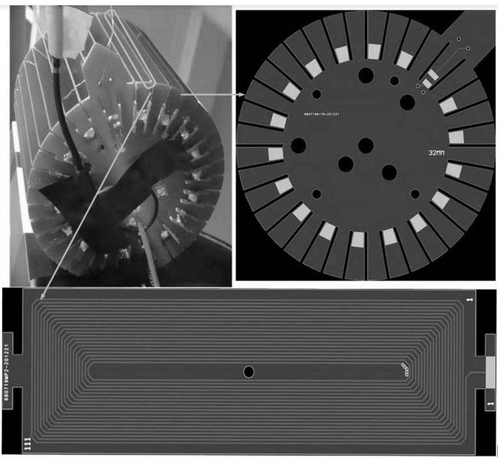
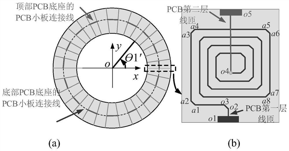
[0048] like figure 1 As shown, the PCB Rogowski coil in the embodiment is composed of 36 two-layer PCB boards with 40 turns and 2 PCB bases. 2 PCB bases fix and connect these 36 small PCB boards together. In order to avoid electromagnetic radiation and electromagnetic interference at the right angle of the PCB wire turn, obtuse angles are usually used instead of right angles at the corners of the wire turns. In order to ...


PUM


Abstract

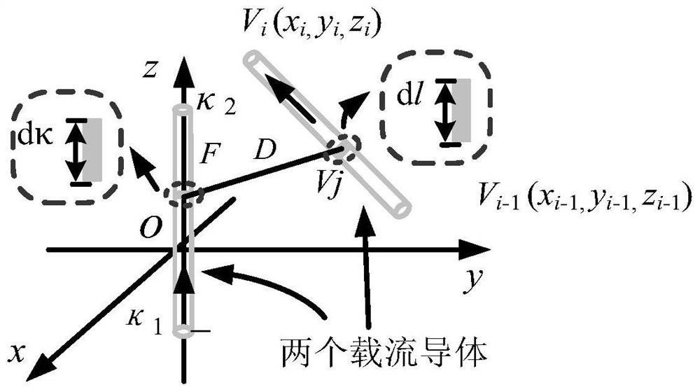
The invention discloses a rapid calculation method for the sensitivity of a PCB Rogowski coil current sensor, and the method comprises the steps: setting one point in a PCB Rogowski coil as the original point of a three-dimensional rectangular coordinate system, setting the geometric center of the PCB Rogowski coil as the original point of the three-dimensional rectangular coordinate system if the PCB Rogowski coil is geometrically symmetric, and setting the point in the PCB Rogowski coil as the original point of the three-dimensional rectangular coordinate system; the geometric symmetry axis of the PCB Rogowski coil is the z axis of the coordinate system; wire turn section endpoint numbering is carried out on the intersection point of wire turn routing of the PCB Rogowski coil and the two endpoints of the coil in sequence; storing the serial numbers of the wire turn points and the coordinates of each wire turn point in a matrix; calculating mutual inductance between any two straight conductors in the space; calculating the mutual inductance between the PCB Rogowski coil and the current-carrying conductor; according to the basic working principle of the Rogowski coil current transformer, the sensitivity of the Rogowski coil is obtained when wires with any positions and any shapes are measured. The method is high in universality and convenient to calculate, a program is easy to compile for calculation, and the design time is saved; no empirical formula exists in the calculation process, and the calculation precision is high.

Description

technical field [0001] The invention relates to the technical field of alternating current measurement, in particular to a method for quickly calculating the sensitivity of a PCB Rogowski coil current sensor. Background technique [0002] Current sensors play an important role in electrical safety engineering. The Rogowski coil current sensor is referred to as the Rogowski coil (Rogowski coil) current sensor, also known as the differential current sensor. It is named after the German physicist Walter Rogowski and has been used for more than 100 years. It is considered to be the best measurement tool for measuring AC current and transient large current. In recent years, various types of Rogowski coil current transformers based on printed circuit board (PCB) technology have not only become a research hotspot, due to their not easy deformation, flexible shape and size, no magnetic saturation, easy production and low cost, and no Rogowski coils with uniform distribution of tur...

Claims


Application Information

Patent Timeline
Patent Type & Authority Applications(China)
IPC IPC(8): G01R35/02G01R19/00G06F17/12G06F17/16
CPCG01R35/02G01R19/0092G06F17/12G06F17/16
Inventor 何怡刚刘晓宇
Owner WUHAN UNIV
Learn More