


Quick Research
Generate reliable direction feasibility study reports for your R&D in just a few steps.

Technical Q&A
Discover and master advanced knowledge NOW. Basics, ideas, possibilities, all at once.

Find Solutions
As an expert in R&D theories, this can generate solutions to your technical problems instantly.

Evaluate Feasibility
Analyze your overall solution with one click, know your potential R&D risks in advance.

Monitor Landscape
Get weekly tech updates, stay abreast of the latest tech innovations and key insights.
Anti-gravity power generation device
A power generation device and anti-gravity technology, which is applied in the energy field to achieve the effect of reducing failure rate, reducing energy consumption and reliable output
- Summary
- Abstract
- Description
- Claims
- Application Information
AI Technical Summary
Problems solved by technology
Method used
Image

Examples
Embodiment 1
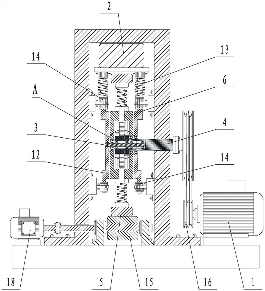
[0043] Such as Figure 1 to Figure 4 The shown anti-gravity power generation device includes a permanent magnet power generation device 1, a counterweight 2, a main shaft 3 fixedly connected to the counterweight 2, an output shaft 4 rotatably matched with the main shaft 3, a driven outer wheel 5 connected to each other and a driven Driven inner wheel 6, a traction device for driving the driven outer wheel 5 to rotate; the main shaft 3 passes through the driven inner wheel 6;
[0044] It also includes a gravity converter connected to the inner diameter end of the driven inner wheel 6 and the outer diameter end of the main shaft 3, the gravity converter is used to convert the gravity of the counterweight 2 acting on the main shaft 3 into compensation power for its own rotation;
[0045] The output end of the gravity converter is fixedly connected with the output shaft 4 , and the output shaft 4 is used to provide power for the permanent magnet generator 1 .
[0046] The gravity...
Embodiment 2
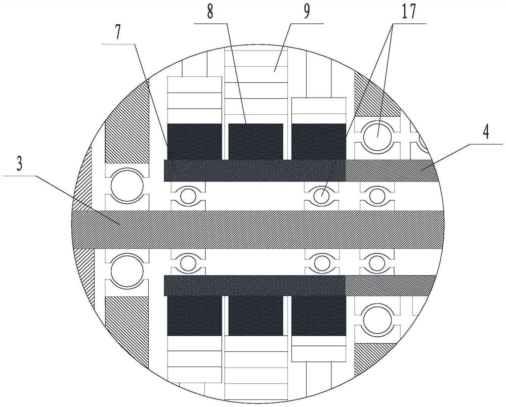
[0049] Such as Figure 1 to Figure 4 In the shown anti-gravity power generation device, on the basis of Embodiment 1, the rack 9 is located on two opposite inner walls of the gear frame 10 , and the ratchet 8 is located inside the gear frame 10 .
[0050] The ratchet 8 is a tooth-less ratchet; along the rotation direction of the driven inner wheel 6 , several ratchets 8 mesh with their corresponding racks 9 sequentially.
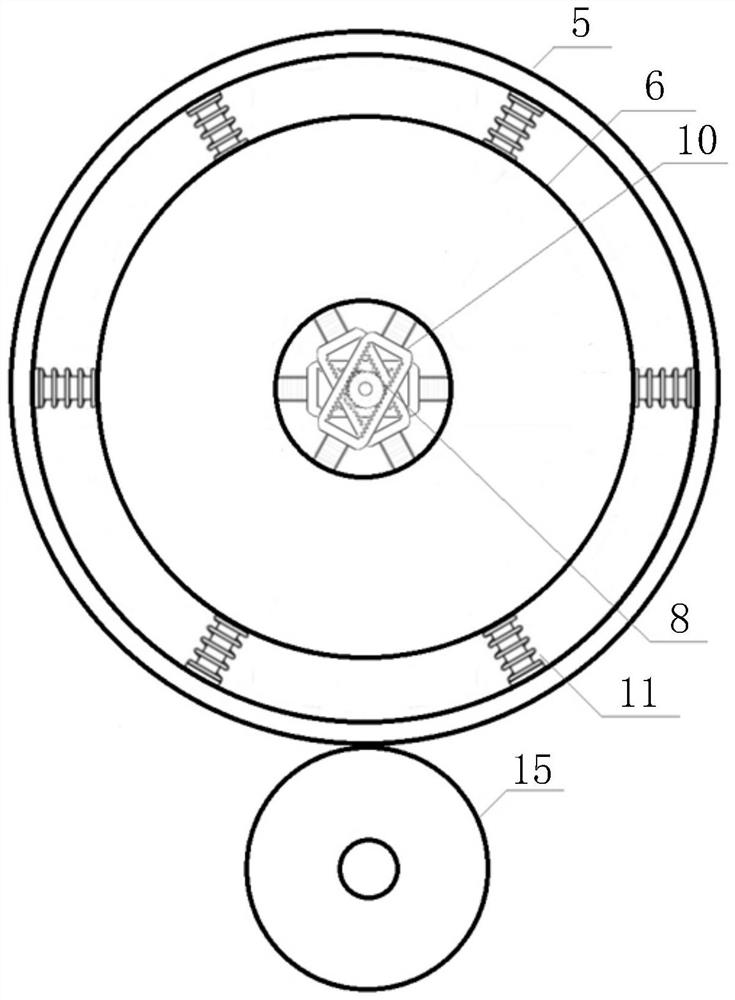
[0051] Between the driven outer wheel 5 and the driven inner wheel 6 are connected a plurality of ring-shaped and evenly distributed restoring elastic members 11 .
[0052] The counterweight body 2 is located on the counterweight support frame 12 , and the counterweight support frame 12 transmits the weight and pressure to the main shaft 3 . The upper and lower ends of the counterweight support frame 12 are slidingly matched with the sliding bearing 14 in the longitudinal direction, and the sliding bearing 14 is fixed relative to the earth. Between the sli...
Embodiment 3
[0058] In this embodiment, on the basis of Embodiment 2, the anti-gravity power generation device of the present application is verified:
[0059] It is known that the gravitational potential energy Ep=mgh (Ep is the gravitational potential energy, m is the mass, g is the gravitational acceleration, and h is the height of the object from the reference plane).
[0060] In this embodiment, a driven outer wheel with an outer diameter of 1 m, a driven inner wheel with an outer diameter of 0.8 m, a weight of 2000 kg, and a total of 8 gravity converters are used. Under the action of the counterweight, the vertical travel distance of the gravity converter between the driven inner wheel and the driven outer wheel is set to 5cm (that is, the maximum unidirectional movement distance of a single ratchet on the corresponding rack is 5cm).
[0061] It can be drawn that the driven inner wheel and the driven outer wheel rotate a circle of 360°, and the total stroke of all gravity converters ...
PUM
 Abstract
Description
Claims
Application Information
 - R&D Engineer
- R&D Manager
- IP Professional
- Industry Leading Data Capabilities
- Powerful AI technology
- Patent DNA Extraction
Browse by: Latest US Patents, China's latest patents, Technical Efficacy Thesaurus, Application Domain, Technology Topic, Popular Technical Reports.
© 2024 PatSnap. All rights reserved.Legal|Privacy policy|Modern Slavery Act Transparency Statement|Sitemap|About US| Contact US: help@patsnap.com