
High-voltage electronic switch circuit system

An electronic switch and circuit system technology, applied in the direction of high-efficiency power electronic conversion, control/regulation system, electrical components, etc., can solve problems such as the inability to guarantee the safety of the whole system and the inability to guarantee the dynamic voltage equalization balance at all levels in series. Consistent on-state, the effect of improving the output capability of the circuit

Pending Publication Date: 2022-05-31
XIAN MICROELECTRONICS TECH INST
View PDF0 Cites 0 Cited by
  • Summary
  • Abstract
  • Description
  • Claims
  • Application Information

AI Technical Summary

Problems solved by technology

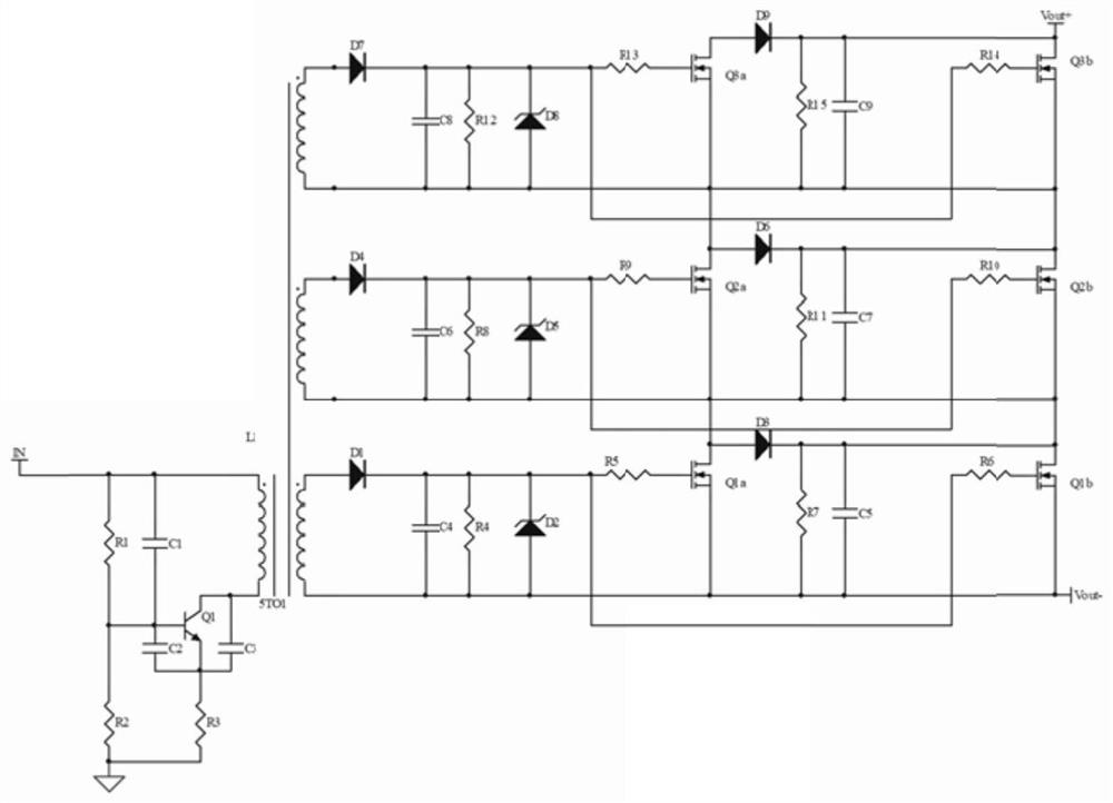
[0004] Existing high-voltage electronic switches have no isolation characteristics. When the power output stage device is broken down by high voltage and fails, the high voltage will be applied reversely to the control terminal through the line, and even to the front stage of the switch circuit, which cannot guarantee the safety of the whole system
[0005] The existing series structure of high-voltage electronic switches adopts the method of connecting the drain and source of the power output tube in parallel with the same resistance resistor to realize the voltage equalization of each stage of the series components. However, this structure only completes the static voltage equalization between the stages of the series output structure. Unable to guarantee the dynamic voltage equalization balance when the stages are turned on and off in series

Method used


Image

  • High-voltage electronic switch circuit system

Examples


Embodiment Construction

[0029] The present invention will be further described in detail below with reference to specific embodiments, which are to explain rather than limit the present invention.

[0030] In order to make those skilled in the art better understand the solutions of the present invention, the technical solutions in the embodiments of the present invention will be clearly and completely described below with reference to the accompanying drawings in the embodiments of the present invention. Obviously, the described embodiments are only Embodiments are part of the present invention, but not all embodiments. Based on the embodiments of the present invention, all other embodiments obtained by persons of ordinary skill in the art without creative efforts shall fall within the protection scope of the present invention.

[0031] It should be noted that the terms "first", "second" and the like in the description and claims of the present invention and the above drawings are used to distinguish...


PUM


Abstract

The invention provides a high-voltage electronic switch circuit system, which is characterized in that the input side of a transformer is connected with a three-point oscillation structure, a level signal is converted into an alternating current signal, the alternating current signal is transmitted to the output side through the transformer, the output side is of a multi-stage series-parallel circuit structure, each stage of series-parallel circuit structure comprises two VDMOS (Vertical Double-diffused Metal Oxide Semiconductor) tubes which are connected in parallel, the VDMOS tubes of the adjacent stages of parallel circuit structures are connected in series, and the same RCD buffer circuits are connected in parallel between drain electrodes and source electrodes of the VDMOS tubes, so that dynamic and static voltage-sharing balance of each stage of serially connected components is ensured; each series-parallel circuit structure is connected with the transformer by adopting the same winding turn to serve as the driving voltage of the power device of the multi-stage series-parallel circuit structure, so that the conduction state of each stage of power device is ensured to be consistent; therefore, the output capability of the circuit is improved, the reliability of the circuit is improved, and the isolation of a power end and a control end is ensured.

Description

technical field [0001] The invention belongs to the design technology of semiconductor hybrid integrated circuits, in particular to a high-voltage electronic switch circuit system. Background technique [0002] With the invention of high-power semiconductor power devices and the development of power circuits, as an electronic switch for weak electrons to control strong power, it has been widely used in various fields of national economy and people's livelihood such as industrial and agricultural production, national defense, transportation, energy and people's life. However, in many high-voltage or ultra-high-voltage applications, the use of a single device is limited due to its low withstand voltage rating. [0003] The technical implementation of the high-voltage electronic switch circuit in the prior art has the following disadvantages: [0004] The existing high-voltage electronic switch has no isolation feature. When the power output stage device is broken down by high...

Claims


Application Information

Patent Timeline
Patent Type & Authority Applications(China)
IPC IPC(8): H02M3/335H02M1/088H02M1/34
CPCH02M3/33576H02M3/33523H02M1/088H02M1/34Y02B70/10
Inventor 李晨源付伟吴悦
Owner XIAN MICROELECTRONICS TECH INST
Learn More