Real-time monitoring smart bracelet based on Internet of Things technology

An Internet of Things technology and real-time monitoring technology, which is applied in the field of real-time monitoring smart bracelets, can solve problems such as travel control difficulties, positioning system errors, and circuit board structure influences, and achieve good emergency response capabilities, reduce assembly difficulty, and achieve good results.

Active Publication Date: 2022-06-03
深圳市章鸿科技有限公司
View PDF18 Cites 0 Cited by
  • Summary
  • Abstract
  • Description
  • Claims
  • Application Information

AI Technical Summary

Problems solved by technology

[0003] Most of the existing smart bracelets are equipped with a positioning system, but the positioning system often has errors. When the wearer has an accident, the person associated with it needs to search around the location prompted by the positioning system. If the surrounding environment is more complicated, it is very difficult. It may happen that the rescue of the wearer is not timely, especially in today's environment, more and more people like to run and exercise in secluded areas, etc., and many accidents have occurred, and the bracelet is the I prefer to wear the equipment, so in case of an accident or danger, timely feedback of danger signals through the wristband is also a new development direction, and adding an image acquisition device to the wristband is currently more effective. Solution
[0004] In the current smart bracelet application, due to its size limitation, the internal circuit board is very compact. Therefore, when installing a camera on it, the most important thing is the compact design of the camera. However, the current lifting camera is mostly used in mobile phones. For larger parts, the lifting principle is mostly driven by the controller to control some micro motors. The operation and stroke of the motor must also be realized by control components. For wristbands, its volume is small, and the circuit board The structure of the micromotor is also relatively compact, and adding additional control elements to it will undoubtedly affect the structure of the circuit board, and for these micro motors, its stroke control is more difficult, and its only use in the bracelet is also It is used as a vibration motor, it is difficult to use it for camera adjustment

Method used


Image

  • Real-time monitoring smart bracelet based on Internet of Things technology
  • Real-time monitoring smart bracelet based on Internet of Things technology
  • Real-time monitoring smart bracelet based on Internet of Things technology

Examples


Embodiment 1

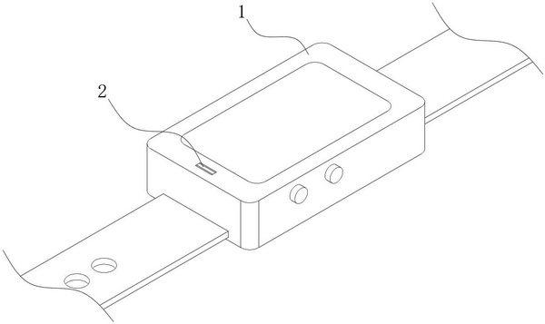
like Figure 1-6 As shown, it is the first embodiment of the present invention, which provides a real-time monitoring smart bracelet based on the Internet of Things technology, including a dial 1, an image acquisition component 2, a magnetic starter 3, a warning module and a self-rotating mechanism 6. Wristbands are fixedly connected to both sides of the bottom of the dial 1, a control unit and a pulse sensor are installed inside the dial 1, an integrated cavity is integrally formed on the dial 1, and the warning module includes a plastic case assembled on the integrated cavity, The pulse sensor is used to monitor the heart rate of the wearer in real time. The image acquisition component 2 is arranged inside the plastic case. The image acquisition component 2 is used to collect the image of the environment around the wearer. The magnetic activation part 3 is arranged inside the plastic case. The part 3 is fixedly connected with the image acquisition assembly 2, the magnetic act...

Embodiment 2

[0040] like Figure 11 As shown in the figure, a fixed magnetic plate 15 is fixedly embedded in the inside of the plastic case, and a linked magnetic plate 16 is arranged on one side of the fixed magnetic plate 15. The linked magnetic plate 16 is slidably arranged inside the plastic casing. The magnetic poles on the opposite side of 15 are the same, there is always a mutually repelling magnetic force between the linked magnetic plate 16 and the fixed magnetic plate 15 , and the top of the linked magnetic plate 16 is fixedly connected with the bottom end of the push-pull plate 11 .

[0041] Specifically, in this embodiment, the return spring 14 in the above-mentioned embodiment is replaced by a fixed magnetic plate 15, and the linkage plate 13 is replaced by a linkage magnetic plate 16. Compared with a small smart bracelet, the linkage magnetic plate 16 and the fixed magnetic plate The installation space required for the plate 15 is small, and the interlocking magnetic plate 16...


PUM


Abstract

The invention belongs to the technical field of smart bracelets, and particularly relates to a real-time monitoring smart bracelet based on the Internet of Things technology, which comprises a dial plate and a wireless communication module, a control unit and a pulse sensor are mounted in the dial plate, an integrated cavity is integrally formed in the dial plate, and the integrated cavity is arranged in the dial plate. The wireless communication module is arranged in the integrated cavity and is at least associated with one external mobile device through a wireless network, the warning module is arranged in the integrated cavity and comprises an image acquisition assembly, a magnetic starting part and a self-rotating mechanism, the image acquisition assembly is arranged in the integrated cavity, the magnetic starting part is arranged in the integrated cavity, and the self-rotating mechanism is arranged in the integrated cavity. And the self-rotating mechanism is arranged in the integrated cavity. According to the invention, the image acquisition assembly can be automatically popped up when the wearer has an accident, and the image acquisition assembly can also rotatably acquire the image of the surrounding environment of the wearer, so that a person associated with the wearer can quickly and accurately judge the position of the wearer.

Description

technical field [0001] The invention belongs to the technical field of smart bracelets, and in particular relates to a real-time monitoring smart bracelet based on the Internet of Things technology. Background technique [0002] The smart bracelet is a small and easy-to-wear smart product. Users usually wear it on the wrist. With the continuous development of electronic technology, smart bracelets can monitor the wearer's heart rate, sleep and exercise. Data, etc., and the monitored data can not only be displayed on the smart bracelet, but also can be synchronized to the mobile device associated with it. For the wearer with poor physical condition, the relevant personnel of the wearer can observe the body data. [0003] Most of the existing smart bracelets are equipped with a positioning system, but the positioning system often has errors. When the wearer has an accident, the person associated with it needs to search around the position indicated by the positioning system. ...

Claims


Application Information

Patent Timeline
Patent Type & Authority Applications(China)
IPC IPC(8): A44C5/00A44C5/14H04B1/3827
CPCA44C5/0015A44C5/14H04B1/385H04B2001/3861Y02D30/70
Inventor 李新龙
Owner 深圳市章鸿科技有限公司
Why Eureka
Try Eureka