Hydraulic linkage type plunger pushing mechanism and plunger diaphragm pump using same

A technology of hydraulic linkage and propulsion mechanism, which is applied to liquid variable capacity machinery, liquid fuel engines, and components of pumping devices for elastic fluids, etc. Stability and other problems, to achieve the effect of no medium loss, stable operation and compact structure

Pending Publication Date: 2022-06-03
SHANGHAI NIKUNI FLUID SYST CO LTD
View PDF0 Cites 1 Cited by
  • Summary
  • Abstract
  • Description
  • Claims
  • Application Information

AI Technical Summary

Problems solved by technology

Because there is a certain gap between the connecting rod and the crankshaft, the operation is not stable and the efficiency is low; and the crankshaft connecting rod structure often takes up more space, making the product bulky and heavy
Due to the structural design flaws of the traditional crankshaft and connecting rod, it is easy to cause increased mechanical wear and damage the structure of the crankshaft and connecting rod. At the same time, it is easy to increase the internal oil temperature of the hydraulic drive mechanism, which will further lead to emulsification of the hydraulic oil of the hydraulic drive mechanism. and loss of lubricating properties
The push-pull structure of the swash plate has a large range of motion, and the sliding friction between the swash plate and the plunger is large, which is prone to wear and tear of parts, excessive power loss, and problems such as oil temperature rise.
[0003] More importantly, in the case of overpressure of the oil pressure, it is easy to bring the risk of damage to the plunger diaphragm pump, such as plunger spring breakage, diaphragm damage, etc.

Method used


Image

  • Hydraulic linkage type plunger pushing mechanism and plunger diaphragm pump using same
  • Hydraulic linkage type plunger pushing mechanism and plunger diaphragm pump using same
  • Hydraulic linkage type plunger pushing mechanism and plunger diaphragm pump using same

Examples


Embodiment 1

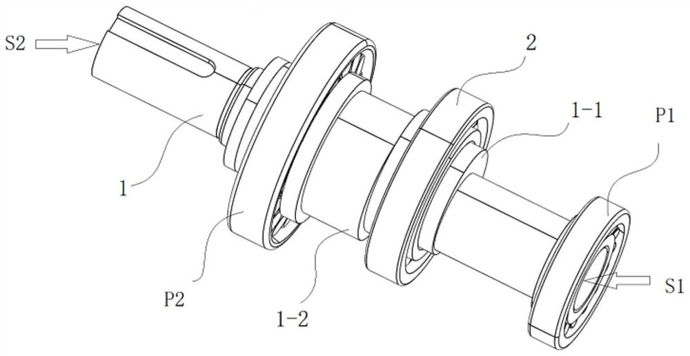
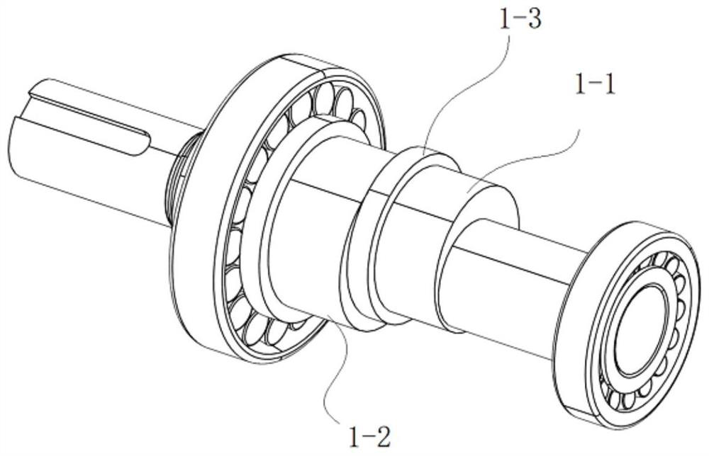
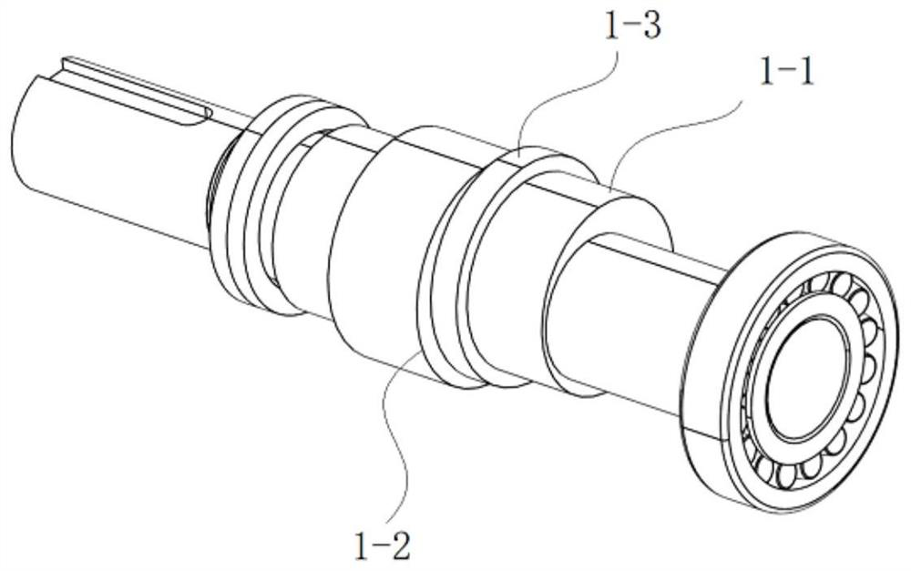
[0064] Example 1: see Figure 1-3 , the hydraulic linkage type plunger pushing mechanism (hereinafter referred to as "the mechanism"), this mechanism is suitable for the plunger diaphragm pump, the mechanism has a crankshaft 1 installed in the low pressure liquid chamber of the plunger diaphragm pump body through the bearing assembly, with The bearing assembly for assembling the crankshaft has a second assembly bearing P2 for assembling the crankshaft to the plunger cylinder, and a first assembly bearing P1 for assembling the crankshaft to the liquid accumulation plate, and the bearing assemblies are all immersed in the low-pressure liquid chamber. The crankshaft is provided with an eccentric portion 1-1.

[0065] combine Figure 4-9 As shown, the wheelbase between the eccentric axis O2 where the eccentric part is located and the axis O1 of the crankshaft 1 is b, and the wheelbase is dimensioned according to needs. An eccentric cylindrical body is formed around the eccentric ...

Embodiment 2

[0070] Embodiment 2: In this embodiment, a driving liquid chamber oil pressure dynamic balance system is arranged between the low pressure liquid chamber 22 and the driving liquid chamber 6 . Considering factors such as the complexity of the overall structural design (in terms of space occupation) and working stability, in this embodiment, the hydraulic dynamic balance system of the driving fluid chamber is integrated into the diaphragm driving link mounting seat.

[0071] Here, the structure after integrating the hydraulic dynamic balance system of the driving fluid chamber at the mounting seat of the diaphragm driving connecting rod is called the diaphragm driving and protection integrator. The diaphragm drive and protection integrator is installed at 7 places. The diaphragm drive and protection integrator can not only drive the diaphragm action, but also prevent the plunger spring from breaking and breaking and the diaphragm tearing. More important Yes also prevents the occ...

Embodiment 3

[0074] Embodiment 3: A plunger diaphragm pump including a hydraulic linkage type plunger pushing mechanism, and a five-plunger plunger diaphragm pump is used as an example for detailed description. see Figure 27-34 , The plunger diaphragm pump has a plunger cylinder 5, five plunger cylinders are arranged on the plunger pump casing, a liquid accumulation plate 7 is arranged on one side of the plunger cylinder 5, the plunger cylinder 5 and the liquid accumulation plate There is a low pressure liquid chamber 22 (for setting low pressure oil) and a driving liquid chamber 6 (for setting driving liquid) between 7. The crankshaft 1 is arranged at the low pressure liquid chamber 22, and the crankshaft extends out of the plunger cylinder 7 and is connected to the cylinder 7. The external motor is connected, the first end S1 of the crankshaft is installed in the first assembly cavity through the first assembly bearing P1, the second end S2 is installed in the second assembly cavity thr...


PUM


Abstract

The invention discloses a hydraulic linkage type plunger pushing mechanism and a plunger diaphragm pump using the same, the mechanism is provided with a crankshaft which is installed in a low-pressure liquid cavity of a plunger diaphragm pump body through a bearing assembly, the crankshaft is provided with an eccentric part, and the eccentric part of the crankshaft is sleeved with a bearing. According to the plunger diaphragm pump, the hydraulic linkage type plunger pushing mechanism is arranged, so that the problem that mechanical abrasion of a swash plate pushing head driving type hydraulic unit in a traditional plunger diaphragm pump is large is solved through the crankshaft, bearing and eccentric design, the bearing is arranged at the eccentric position of the crankshaft, and the outer ring of the bearing and the pushing head are tightly attached and do not generate relative movement; relative movement is achieved through the rolling bearings, the crankshaft pushes the corresponding plungers through the rolling bearings to complete compression action, outer rings of the bearings are not directly abraded with the plungers, factors of oil temperature rise caused by large mechanical action range of a traditional swash plate pushing head and large mechanical abrasion caused by sliding friction are avoided, the oil temperature in a low-pressure liquid cavity is greatly reduced, and the service life of the crankshaft is prolonged. And the oil temperature of the low-pressure liquid chamber is not obviously increased in the actual operation process.

Description

technical field [0001] The invention relates to the technical field of pumps, in particular to a hydraulic linkage type plunger pushing mechanism and a plunger diaphragm pump using the same. Background technique [0002] At present, the plunger pumps on the market are mainly the crankshaft connecting rod structure and the swash plate push-pull structure. Because there is a certain gap between the connecting rod and the crankshaft, the operation is unstable and the efficiency is low; and the crankshaft connecting rod structure often occupies more space, making the product bulky and heavy. Due to the structural design defects of the traditional crankshaft and connecting rods, it is easy to increase the mechanical wear and damage the crankshaft connecting rod structure, and at the same time, it is easy to increase the oil temperature inside the hydraulic drive mechanism, which will further lead to the hydraulic oil of the hydraulic drive mechanism. Emulsification And the loss ...

Claims


Application Information

Patent Timeline
Patent Type & Authority Applications(China)
IPC IPC(8): F04B9/04F04B43/067F04B53/10
CPCF04B9/045F04B43/067F04B53/1002
Inventor 刘凤伟吴新林
Owner SHANGHAI NIKUNI FLUID SYST CO LTD
Why Eureka
Try Eureka