
Spraying, temperature lowering and shaping device for processing outer insulating layer of shielded cable

A technology of outer insulating layer and shielded cable, applied in conductor/cable insulation, electronic waste recycling, recycling technology and other directions, can solve the problems of good local cooling effect and insignificant cooling effect in other parts, and achieve good shaping effect, Avoid the effect of stopping sliding and cooling evenly

Pending Publication Date: 2022-06-03
陈云江
View PDF0 Cites 0 Cited by
  • Summary
  • Abstract
  • Description
  • Claims
  • Application Information

AI Technical Summary

Problems solved by technology

The wire and cable industry is the second largest industry in China after the automobile industry. The satisfaction rate of product varieties and the domestic market share both exceed 90%. During the production and processing of shielded cables, it is necessary to shape the outer insulation layer. Existing During the use of the shaping device, when it adopts air-cooling and water-cooling methods to cool down, the air outlet direction and spraying direction are often single, and the cooling direction is not changed, so that the local cooling effect is good, and the cooling effect of other parts is good. It is not obvious that this is a shortcoming of the prior art. In addition, when discharging, the outer insulating layer will stop sliding due to the friction between the outer insulating layer and the discharging plate during the discharging process. At this time, it is often necessary to work The personnel manually take out the shaped outer insulating layer, which is another shortcoming of the prior art, so a device for processing the outer insulating layer of shielded cables by spraying, annealing and shaping is proposed here to solve the shortcomings of the prior art

Method used


Image

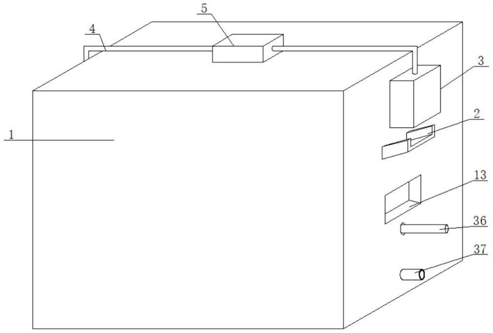
  • Spraying, temperature lowering and shaping device for processing outer insulating layer of shielded cable
  • Spraying, temperature lowering and shaping device for processing outer insulating layer of shielded cable
  • Spraying, temperature lowering and shaping device for processing outer insulating layer of shielded cable

Examples


Embodiment Construction

[0030] The technical solutions in the embodiments of the present invention will be clearly and completely described below with reference to the accompanying drawings in the embodiments of the present invention. Obviously, the described embodiments are only a part of the embodiments of the present invention, rather than all the embodiments. Based on the embodiments of the present invention, all other embodiments obtained by those of ordinary skill in the art without creative efforts shall fall within the protection scope of the present invention.

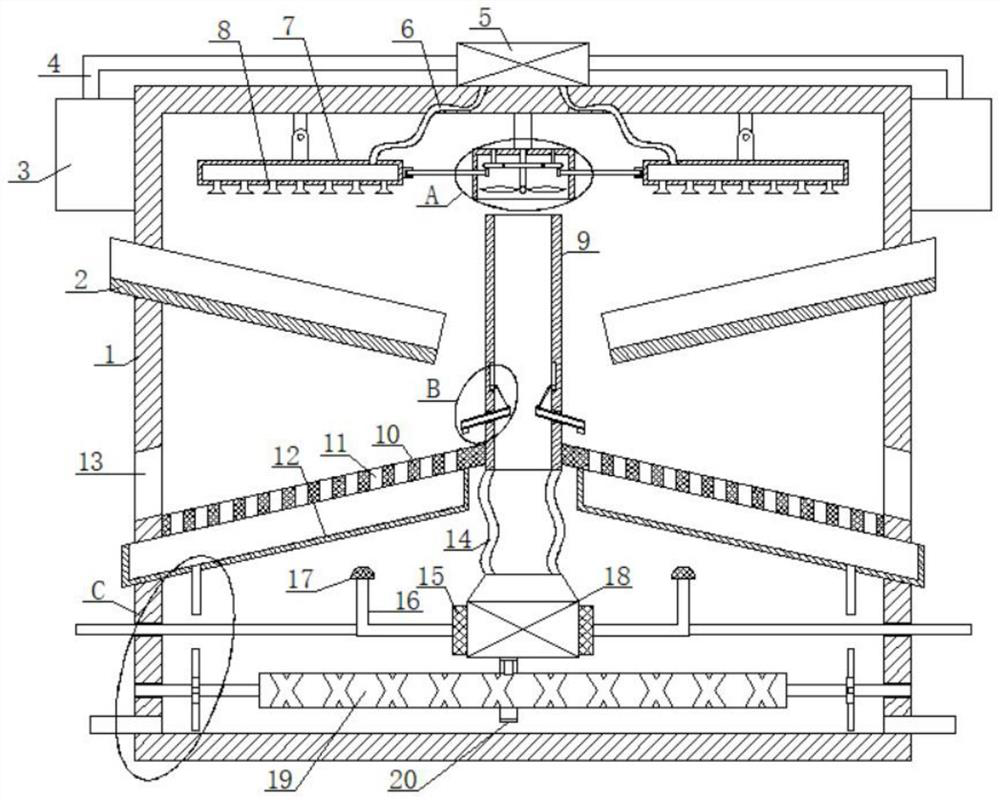
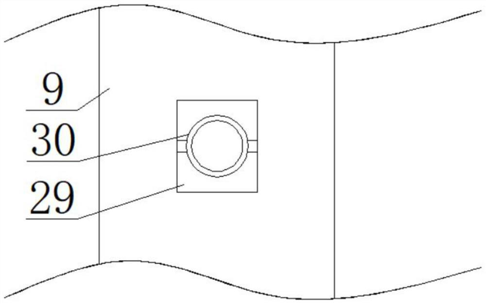
[0031] see Figure 1-7, the present invention provides a technical solution: a shielded cable outer insulation layer processing spray cooling and setting device, including a casing 1, the left and right sides of the casing 1 are installed near the top of the water tank 3, and the top of the casing 1 is installed with a water pump 5 , both the left and right sides of the water pump 5 are plugged with a conduit 4, and the end of the co...


PUM


Abstract

The invention discloses a shielding cable outer insulation layer processing spraying temperature-lowering shaping device which comprises a shell, water tanks are installed at the positions, close to the top, of the left side and the right side of the shell correspondingly, a water pump is installed at the top of the shell, guide pipes are inserted into the left side and the right side of the water pump correspondingly, and the ends, away from the water pump, of the guide pipes are inserted into the tops of the adjacent water tanks; through cooperative use of a series of parts such as a first gear, an air guide pipe and a second gear, the spraying angle of spraying and the air outlet angle of the air guide pipe can be changed, the outer insulating layer is further cooled uniformly, and the shaping effect is good; through cooperative use of a series of components such as a water outlet pipe, an impeller and an L-shaped rod, the water collecting tank can be knocked after cooling and shaping are finished, an inclined plate is further made to vibrate, the shaped outer insulator can be better discharged on the inclined plate, and the situation that sliding is stopped due to friction force is avoided.

Description

technical field [0001] The invention relates to the technical field of cable processing, in particular to a spraying, cooling and temperature-setting device for processing an outer insulating layer of a shielded cable. Background technique [0002] A shielded cable is a transmission line that uses a metal mesh braid to wrap the signal wire. The braid is generally red copper or tinned copper. The wire and cable industry is the second largest industry in China after the automobile industry. The product variety satisfaction rate and domestic market share are both over 90%. During the production and processing of shielded cables, the outer insulation layer needs to be shaped. The existing During the use of the shaping device, when it uses air cooling and water cooling to cool down, the direction of the air outlet and the direction of the spray are often single, and the cooling direction is not converted, so that the local cooling effect is good, and the cooling effect of other ...

Claims


Application Information

Patent Timeline
IPC IPC(8): H01B13/06
CPCH01B13/06Y02W30/82
Inventor 陈云江
Owner 陈云江
Learn More