Charging gun terminal structure and rubber coating mode

A terminal structure and charging gun technology, applied in charging stations, electric vehicle charging technology, circuits, etc., can solve the problems of poor heat dissipation effect, sudden change in crimping position, and high labor cost, and achieve good compression ratio and volume ratio. Reduced gasket parts, good heat dissipation effect

Pending Publication Date: 2022-06-07
WORKERSBEE ELECTRONICS TECH HLDG SUZHOU CO LTD
View PDF0 Cites 0 Cited by
  • Summary
  • Abstract
  • Description
  • Claims
  • Application Information

AI Technical Summary

Problems solved by technology

[0004] Based on this, the object of the present invention is to provide a charging gun terminal structure and a glue-covering method to solve the problem that most of the existing charging guns are machine-added terminals, and the machine-added solid terminals are made of H62 brass material, and the heat dissipation effect is not hollow. Good; the traditional machining process has high labor costs and low work efficiency; in addition, the waterproof problem of the crimping part of the tail should be considered in the machine-added terminal. In order to ensure the waterproof level, a gasket needs to be added to increase the cost; each batch of machine-added terminals needs Guaranteed dimensional accuracy, high dimensional stability of mold stamping terminals; technical problem that the hexagonal crimping at the tail of the machined terminal undergoes high temperature shock and the crimping position changes suddenly, resulting in failure to charge

Method used


Image

  • Charging gun terminal structure and rubber coating mode
  • Charging gun terminal structure and rubber coating mode

Examples


Embodiment 1

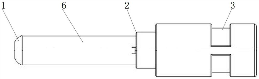
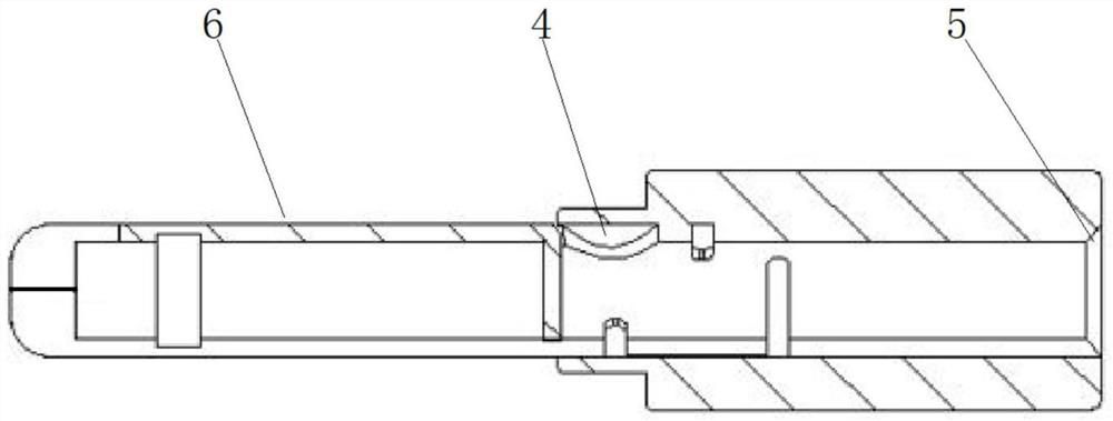
[0023] A charging gun terminal structure and encapsulation method, comprising a terminal main body 6, the inner end of the terminal main body 6 away from the chamfer 5 is provided with a pin, and the diameter of the pin is 6mm, and the 6mm pin is conductive for the main body of the charging gun to realize the charging function , one end of the terminal main body 6 is provided with a stamping terminal head chamfer 1, the position of the head chamfer meets the requirements of the insertion force, and the outer side of the terminal main body 6 is provided with a rubber-coated terminal 2, and the length of the rubber-coated terminal 2 is 25mm. For the effect of effective insulation, the outer side of the terminal body 6 is provided with a buckle position 3 on the side of the end point 2 of the rubber coating. There is a circular baffle 4 with an inner groove. The circular baffle 4 with an inner groove can better solve the problem of mold forming. One end of the terminal body 6 is p...


PUM


Abstract

The invention discloses a charging gun terminal structure and a rubber coating mode, and relates to the field of charging gun accessories, the charging gun terminal structure comprises a terminal main body, one end of the terminal main body is provided with a stamping terminal head chamfer, the outer side of the terminal main body is provided with a rubber coating end point, and the outer side of the terminal main body is provided with a buckling position on one side of the rubber coating end point. An inner groove circular baffle plate is arranged on the inner side of the rubber coating end point in the terminal main body, and a chamfer is arranged at one end in the terminal main body. Compared with a machining terminal, after the stamping terminal is formed, the cost is greatly reduced by more than 50%, the production efficiency is improved by 100%, the test heat dissipation effect is good, the heat dissipation effect is 5 DEG C lower than that of an existing machining terminal, sealing gasket parts are reduced, the stamping terminal is made of a copper alloy material and is easy to form, the material hardness reaches more than 180 degrees, the requirement for 10000 times of plugging and unplugging is met, and the service life of the stamping terminal is prolonged. After the terminal is encapsulated, the internal space is in a sealed state, the test reaches IP68 waterproof and dustproof grade, and the wiring mode is B-type crimping, so that the terminal is more stable, and the compression ratio plot ratio is better.

Description

technical field [0001] The invention relates to the field of charging gun accessories, in particular to a charging gun terminal structure and an encapsulation method. Background technique [0002] In order to better protect the environment and save resources, more and more people choose electric vehicles. Electric vehicles use batteries as energy storage power sources, and the batteries are charged by the charging gun on the electric pile, and an important part of the charging gun is the terminal. . [0003] Most of the existing charging guns are machined terminals, and the machined ones are made of H62 brass material for solid terminals. The heat dissipation effect is not as good as that of hollow ones; the traditional machining process has high labor costs and low work efficiency; in addition, the machined terminals need to consider the tail. For the waterproof problem at the crimping point, in order to ensure the waterproof level, it is necessary to add a gasket to incre...

Claims


Application Information

Patent Timeline
Patent Type & Authority Applications(China)
IPC IPC(8): H01R13/02H01R13/03H01R13/52H01R4/18H01R43/048H01R43/16H01R43/24H05K7/20B60L53/16
CPCH01R13/02H01R13/03H01R13/521H01R4/18H01R43/16H01R43/24H01R43/048H05K7/20B60L53/16H01R2201/26Y02T90/14
Inventor 王继华杨涛李号江杨伟
Owner WORKERSBEE ELECTRONICS TECH HLDG SUZHOU CO LTD
Why Eureka
Try Eureka