Cooling system capable of achieving automatic liquid injection function and automatic liquid injection method

A technology of cooling system and coolant, which is applied in the direction of control/regulation system, cooling/ventilation/heating renovation, refrigeration machine, etc., which can solve the problems affecting the utilization rate of equipment, affecting the operation of electrical equipment, and cumbersome operation process, so as to improve heat dissipation Efficiency and equipment utilization, reduction of labor maintenance and maintenance costs, and the effect of simplifying the injection process

Pending Publication Date: 2022-06-07
DELTA ELECTRONICS (SHANGHAI) CO LTD
View PDF0 Cites 0 Cited by
  • Summary
  • Abstract
  • Description
  • Claims
  • Application Information

AI Technical Summary

Problems solved by technology

Usually, the above-mentioned exhaust process takes a long time, and after the air is discharged, the pressure of the coolant drops, and the cooling system needs to be supplemented with liquid. Affect the operation of other electrical equipment on site
[0004] In addition, during the normal operation of the cooling system, there is still a loss of coolant, and maintenance personnel are required to replenish the coolant in time, otherwise, the pressure of the coolant in the pipeline will drop, and the heat dissipation efficiency will decrease, resulting in equipment alarms or reduced power operation.
At the same time, in order to ensure safety, it needs to be shut down during the rehydration process, which affects the utilization rate of equipment and increases maintenance costs

Method used


Image

  • Cooling system capable of achieving automatic liquid injection function and automatic liquid injection method
  • Cooling system capable of achieving automatic liquid injection function and automatic liquid injection method
  • Cooling system capable of achieving automatic liquid injection function and automatic liquid injection method

Examples


Embodiment Construction

[0052] For a more detailed and complete description of the present invention, reference may be made to the accompanying drawings and the following various embodiments, in which like numerals represent the same or similar components. On the other hand, well-known components and procedures have not been described in the embodiments in order not to unnecessarily limit the present invention. In addition, for the purpose of simplifying the drawings, some well-known and conventional structures and elements are shown in a simplified and schematic manner in the drawings.

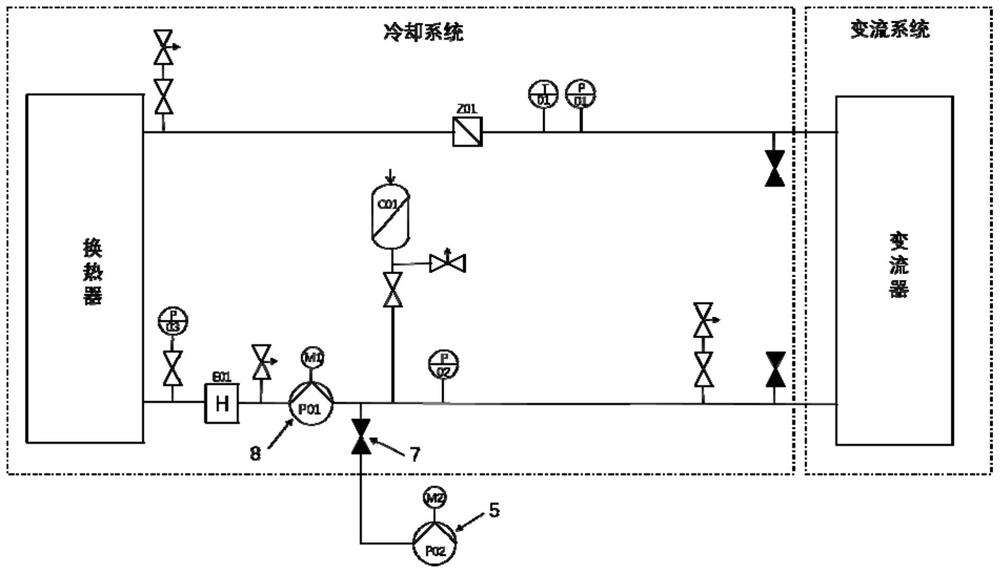
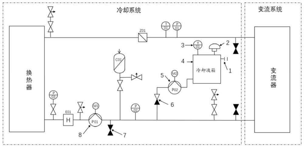
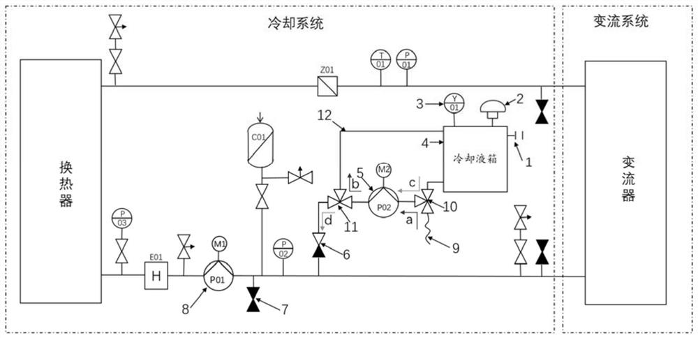
[0053] According to a preferred embodiment of the present invention, see figure 2 , a cooling system capable of realizing automatic liquid injection function is provided, comprising a heat exchanger, a converter and a liquid cooling pipeline connecting the heat exchanger and the converter. The liquid cooling pipeline is also provided with a circulating pump 8 . The cooling system further includes: a cooling liqui...


PUM


Abstract

The invention discloses a cooling system capable of realizing an automatic liquid injection function and an automatic liquid injection method. The cooling system comprises a heat exchanger, a converter, a liquid cooling pipeline connected with the heat exchanger and the converter, a cooling liquid tank, a liquid injection pump and a control unit. A liquid level sensor of the cooling liquid tank detects the liquid level of the cooling liquid tank in real time, when the liquid injection pump is started, cooling liquid from the cooling liquid tank is injected into the liquid cooling pipeline, and the control unit controls starting and stopping operation of the liquid injection pump, starting and stopping operation of the circulating pump, a set dynamic hydraulic threshold value and a set static hydraulic threshold value. When the liquid level of the cooling liquid tank reaches an upper limit value, the cooling liquid is injected into the liquid cooling pipeline through the liquid injection pump; and when the pressure of the cooling liquid in the liquid cooling pipeline reaches the upper limit value of the static hydraulic threshold value, the liquid injection pump is closed, starting and stopping operation is executed by means of the circulating pump according to a preset circulation period, and the circulating pump drives the cooling liquid to circularly flow in the liquid cooling pipeline when being started. Compared with the prior art, the cooling system is optimized, the liquid injection process is simplified, and automatic liquid injection is achieved.

Description

technical field [0001] The invention relates to the field of converter cooling systems, in particular to a cooling system and an automatic liquid injection method capable of realizing automatic liquid injection function. Background technique [0002] like figure 1 As shown, the existing energy storage converters are often equipped with a cooling system with cooling liquid as the heat transfer medium. Before operation, an appropriate amount of cooling liquid needs to be injected into the pipeline of the cooling system. Valve 7 connects external priming pump 5 to the cooling system. At the same time, before using the liquid injection pump 5, the pump body needs to be filled with liquid in advance, and the process is complicated. Improper operation of the filling pump will also cause coolant leakage. [0003] Due to the tortuous distribution of pipelines in the cooling system of the converter, it is difficult to discharge the air in the pipelines at one time during the liquid...

Claims


Application Information

Patent Timeline
Patent Type & Authority Applications(China)
IPC IPC(8): H05K7/20
CPCH05K7/20218H05K7/20272F28F27/00F28D15/00F28D2021/0028F28F2265/18H01M10/6568H05K7/20927H05K7/20945Y02E60/10F25B45/00F28F2250/08G05D9/12
Inventor 杨涛陈俊匡经舷王东黄顺喜陈其全
Owner DELTA ELECTRONICS (SHANGHAI) CO LTD
Why Eureka
Try Eureka