Supercharge Your Innovation With Domain-Expert AI Agents!

Multi-level power conversion system and method

A power conversion and power supply technology, applied in the direction of output power conversion devices, control systems, converter types, etc., to achieve the effect of improving efficiency

Pending Publication Date: 2022-06-07
HUAWEI DIGITAL POWER TECH CO LTD
View PDF0 Cites 0 Cited by
  • Summary
  • Abstract
  • Description
  • Claims
  • Application Information

AI Technical Summary

Problems solved by technology

Therefore, the power factor of the AC / DC stage may be close to the unity required by various international standards

Method used


Image

  • Multi-level power conversion system and method
  • Multi-level power conversion system and method
  • Multi-level power conversion system and method

Examples


Embodiment Construction

[0055] The making and using of presently preferred embodiments are discussed in detail below. It should be appreciated, however, that the present disclosure provides many applicable inventive concepts that can be embodied in a wide variety of specific contexts. The specific embodiments discussed are merely illustrative of specific ways to make and use the disclosure, and do not limit the scope of the disclosure.

[0056] This disclosure will describe a preferred embodiment in a specific context, namely an integrated motor drive and isolated battery charger power conversion system. However, the present disclosure also applies to various power conversion systems. Hereinafter, various embodiments will be described in detail with reference to the accompanying drawings.

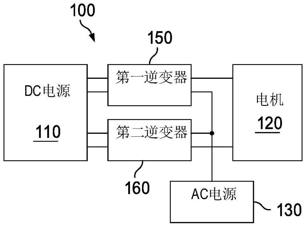
[0057] figure 1 Power conversion systems according to various embodiments of the present disclosure are shown. The power conversion system 100 includes a direct current (DC) power source 110 , a motor 120 , an...


PUM


Abstract

A system includes a first power conversion device connected to a first power source, a first isolated power conversion device connected to the first power source, and a second power conversion device connected to the first isolated power conversion device, where an output of the first power conversion device and an output of the second power conversion device are connected in series, and an output of the series connection of the first power conversion device and the second power conversion device is used for driving the motor.

Description

technical field [0001] The present disclosure relates to high efficiency power conversion systems and, in particular embodiments, to integrated motor drives and isolated battery charger systems. Background technique [0002] The power electronics industry has experienced rapid growth due to continuous improvements in the exponential development of new technologies. With the further development of power electronics technology, vehicle battery chargers have become a key element in some new energy applications. One of the most important new energy applications is electric vehicles (EVs). Different EVs are equipped with batteries of different capacities and voltages. EVs require suitable chargers to charge various batteries. [0003] Onboard battery chargers include electronic circuits for converting alternating current (AC) power into direct current (DC) power. Onboard battery chargers can include AC / DC stages and DC / DC stages. The input of the AC / DC stage is connected to ...

Claims


Application Information

Patent Timeline
IPC IPC(8): H02M3/335H02M7/483H02M3/28H02J7/00H02J7/02B60L50/60B60L53/24H02M7/487H02M1/00H02M7/797
CPCH02M3/335H02M7/487H02M7/483H02M3/285H02M3/33584H02M7/797H02J7/02H02J7/0063B60L53/24B60L50/60H02J2207/20Y02T10/92H02M1/0077H02M1/0058H02M1/007H02M1/0043H02M3/1552H02M1/0074B60L2210/10B60L2210/30B60L2210/40B60L2220/00H02P27/06
Inventor 朱辉斌傅电波戴和平叶立明
Owner HUAWEI DIGITAL POWER TECH CO LTD
Features
  • R&D
  • Intellectual Property
  • Life Sciences
  • Materials
  • Tech Scout
  • Unparalleled Data Quality
  • Higher Quality Content
  • 60% Fewer Hallucinations
Learn More