Semiconductor wafer groove type cleaning machine

A technology for semiconductors and cleaning machines, applied in semiconductor/solid-state device manufacturing, liquid cleaning methods, conveyor objects, etc., to achieve uniform moving speed, increase transportation speed, and avoid cleaning liquid mixing

Active Publication Date: 2022-06-10
ZHICHENG SEMICON EQUIP TECH (KUNSHAN) CO LTD
View PDF7 Cites 4 Cited by
  • Summary
  • Abstract
  • Description
  • Claims
  • Application Information

AI Technical Summary

Problems solved by technology

[0004]Based on the technical problem that the multiple transport speeds in the existing wafer cleaning process are slow and easily cause the production efficiency of the entire production line to be slow, the present invention proposes a semiconductor wafer Tank cleaner

Method used


Image

  • Semiconductor wafer groove type cleaning machine
  • Semiconductor wafer groove type cleaning machine
  • Semiconductor wafer groove type cleaning machine

Examples


Embodiment Construction

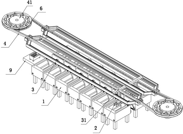
[0037] like Figure 4 and Figure 7 As shown, in order to realize the adjustment of the moving speed of the manipulator, specifically, the speed change mechanism also includes a rotating disc 41 driven by a motor, and the two rotating discs 41 are mirror-symmetrically distributed in the length direction of the synchronous belt 4, and the first cylinder 5 Fixedly installed on the radial direction of the outer surface of the rotating disk 41, the meshing teeth 6 are fixedly installed on the piston rod outer end of the first cylinder 5 to realize radial expansion and contraction. into a gear with a fixed diameter, when the speed of the synchronous belt 4 needs to be adjusted, the first cylinder 5 only needs to drive the meshing teeth 6 to expand and contract to change the diameter of the gear, and the purpose of speed regulation of the synchronous belt 4 can be realized. A plurality of first cylinders 5 are distributed in a circular array with the axis of the rotating disc 41 as...


PUM


Abstract

The invention belongs to the technical field of semiconductor production and manufacturing, and particularly relates to a semiconductor wafer groove type cleaning machine which comprises a cleaning groove and a mechanical arm used for taking a flower basket into the cleaning groove. The mechanical arm comprises a mechanical claw, the flower basket is taken into the cleaning tank through the mechanical claw to be cleaned, and a guiding and positioning mechanism is arranged above the mechanical arm. According to the groove type cleaning machine for the semiconductor wafer, by arranging the speed change mechanism, when the moving speed of the mechanical arm needs to be adjusted, meshing teeth are driven by stretching out and drawing back of the first air cylinder to make meshing movement with the synchronous belt, the synchronous belt is driven, and the moving speed of the synchronous belt and the mechanical arm is adjusted at the same time; and the moving speed of the manipulator is controlled, and the manipulator after speed regulation has the effect of uniform and stable moving speed.

Description

technical field [0001] The invention relates to the technical field of semiconductor wafer cleaning, in particular to a semiconductor wafer tank cleaning machine. Background technique [0002] Wafer cleaning is a process of removing dirt by chemical cleaning of the entire batch or a single wafer, by immersion or spraying of chemicals. The main purpose is to remove pollutants on the surface of the wafer, such as dust particles, Impurities such as organic matter, inorganic matter and metal ions. [0003] In the existing wafer tank cleaning equipment, the wafer needs to be cleaned through multiple cleaning tanks filled with different chemical cleaning solutions, and each cleaning tank needs to be purified in a cleaning tank with clean water after cleaning , to prevent the chemical cleaning solution stained on its surface from mixing into other cleaning tanks, which makes each cleaning time longer, coupled with the characteristics that need to be lifted and transported and the ...

Claims


Application Information

Patent Timeline
Patent Type & Authority Applications(China)
IPC IPC(8): B08B3/04B08B3/08B08B9/087B08B13/00H01L21/677H01L21/687
CPCB08B3/047B08B3/08B08B9/087B08B13/00H01L21/67703H01L21/67706H01L21/68707Y02P70/50
Inventor 杨仕品孙先淼华斌
Owner ZHICHENG SEMICON EQUIP TECH (KUNSHAN) CO LTD
Why Eureka
Try Eureka