Sludge treatment system for slurry circulation in drilling engineering

A sludge treatment and slurry technology, which is used in sludge treatment, water/sludge/sewage treatment, mining wastewater treatment, etc., to save labor, reduce equipment volume, and improve mixing effect.

Active Publication Date: 2022-06-10
SHANDONG PROVINCIAL COAL GEOLOGICAL PLANNING EXPLORATION & RES INST
View PDF8 Cites 0 Cited by
  • Summary
  • Abstract
  • Description
  • Claims
  • Application Information

AI Technical Summary

Problems solved by technology

[0004] In view of the deficiencies and defects in the prior art, the purpose of the invention is to provide a sludge treatment system for drilling engineering mud circulation, which solves the current problem of mud When recycling waste sludge, the sedimentation tank is sprayed with chemicals. In order to make the sludge and chemicals mix well, it is necessary to install multiple mixing devices in the sedimentation tank, and the volume of each mixing device is also relatively large. Not only It causes a certain waste of consumables, and there are many mixing dead angles, which leads to the problem that the treatment of sludge cannot achieve the desired effect

Method used


Image

  • Sludge treatment system for slurry circulation in drilling engineering
  • Sludge treatment system for slurry circulation in drilling engineering
  • Sludge treatment system for slurry circulation in drilling engineering

Examples


Embodiment Construction

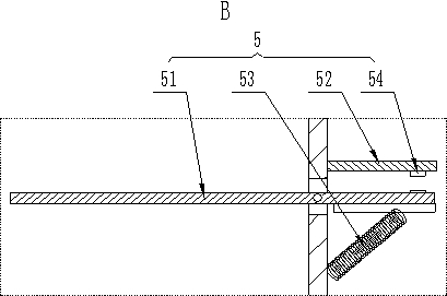
[0035] like image 3 As shown, in the present embodiment, the specific structure of the start-stop switch 5 of another structure is as follows: it includes a rotating plate 51 and a detection plate 52, the rotating plate 51 passes through the comprehensive mixing pipe 2, and the middle part of it can be rotated up and down and is hinged on the On the comprehensive mixing pipe 2, the rotating plate 51 is connected to the comprehensive mixing pipe 2 through a spring 53 outside the comprehensive mixing pipe 2. In the balanced state without external force, the rotating plate 51 is in a horizontal state, and the detection plate 52 is set on the comprehensive mixing pipe 2. On the outer wall, and at the top of the rotating plate 51, the bottom of the detection plate 52 is provided with a proximity sensor 54 that can detect the proximity of the rotating plate 51, and the proximity sensor 54 is connected to the spraying device 3 and the mixing mechanism 4 for signal, That is, when the...


PUM


Abstract

The invention discloses a sludge treatment system for slurry circulation in drilling engineering, which comprises a vibrating screen and a settling pond, and an obliquely arranged converging pipe and a vertically arranged comprehensive mixing pipe are sequentially arranged between a sludge outlet of the vibrating screen and the settling pond; the comprehensive mixing pipe is provided with a spraying device capable of spraying a medicament to the sludge and a uniform mixing mechanism capable of uniformly mixing the sludge and the medicament, and the spraying device and the uniform mixing mechanism are jointly controlled by a switch capable of automatically starting and stopping according to the falling condition of the sludge; the confluence pipe, the comprehensive mixing pipe and the spraying device are arranged, chemicals can be synchronously sprayed and added while sludge is conveyed to the sedimentation tank, the uniform mixing mechanism is further arranged, the sludge and the chemicals are further uniformly mixed under the mixing of the uniform mixing mechanism, and compared with the existing mode that a stirring device is directly additionally arranged in the sedimentation tank, the equipment size is reduced, and the equipment cost is reduced. Equipment consumables are saved, no dead angle exists in mixing, the mixing effect is improved, and the purposes of environmental protection and green exploration are achieved.

Description

technical field [0001] The invention belongs to the technical field of sludge treatment, in particular to a sludge treatment system for drilling mud circulation. Background technique [0002] In drilling engineering such as geological and mineral drilling engineering, mud circulation is an essential and important part of it. In this process of mud circulation, a certain amount of waste mud sludge will be produced, and these sludges contain many substances harmful to the environment, such as oils, chemical additives, heavy metals (such as mercury, copper, chromium and lead, etc. ), macromolecular organic compounds, alkaline substances, etc. If they are not treated, they will be discharged again or left in the sedimentation tank, which will cause secondary pollution and seriously endanger the ecological environment. [0003] With the strengthening of environmental protection awareness and the requirements of green exploration work, more and more construction sites will add ch...

Claims


Application Information

Patent Timeline
Patent Type & Authority Applications(China)
IPC IPC(8): C02F11/00B01F33/82B01F27/95C02F103/10
CPCC02F11/00C02F2103/10
Inventor 王怀洪沈立军朱裕振周明磊刘雪孙超张文艳张心彬汝亮
Owner SHANDONG PROVINCIAL COAL GEOLOGICAL PLANNING EXPLORATION & RES INST
Why Eureka
Try Eureka