Integrated assembly unit for accessories of refrigeration equipment for cold chain

A refrigeration equipment, integrated technology, applied in the direction of welding equipment, metal processing equipment, gas flame welding equipment, etc., can solve the problems of copper tube thermal deformation, cumbersome assembly process, copper tube wear, etc., to avoid copper tube deformation, ensure The effect of assembly quality

Pending Publication Date: 2022-06-17
李超
View PDF0 Cites 0 Cited by
  • Summary
  • Abstract
  • Description
  • Claims
  • Application Information

AI Technical Summary

Problems solved by technology

[0005] In order to overcome the cumbersome assembly process of the existing copper tubes and U-shaped joints, and the shortcomings of causing wear to the copper tubes

Method used


Image

  • Integrated assembly unit for accessories of refrigeration equipment for cold chain
  • Integrated assembly unit for accessories of refrigeration equipment for cold chain
  • Integrated assembly unit for accessories of refrigeration equipment for cold chain

Examples


Embodiment 1

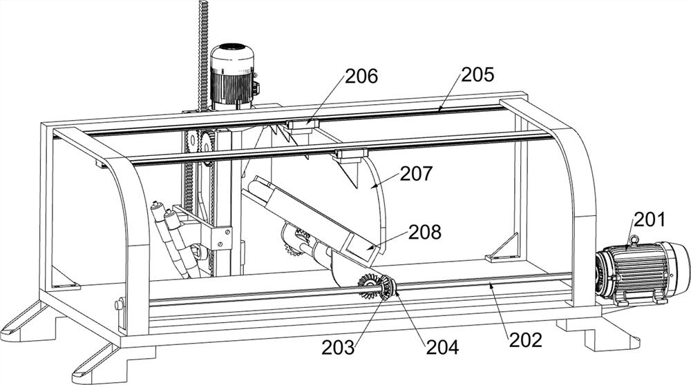
[0032] An integrated assembly unit of refrigeration equipment accessories for cold chain, such as Figure 1-10 As shown, it includes a mounting seat 1, a fixing plate 2, a supporting frame 3, a supporting folding plate 4, an automatic feeding unit and a flare welding unit; the mounting seat 1 is provided with four, and the upper sides of the four mounting seats 1 are fixed together A fixed plate 2 is connected; a support frame 3 is fixedly connected to the upper front part of the fixed plate 2; ; The upper rear of the fixed plate 2 is connected with an automatic feeding unit; the automatic feeding unit is connected with the support frame 3; the automatic feeding unit is connected with the support folding plate 4; the automatic feeding unit is connected with a flare welding unit.

Embodiment 2

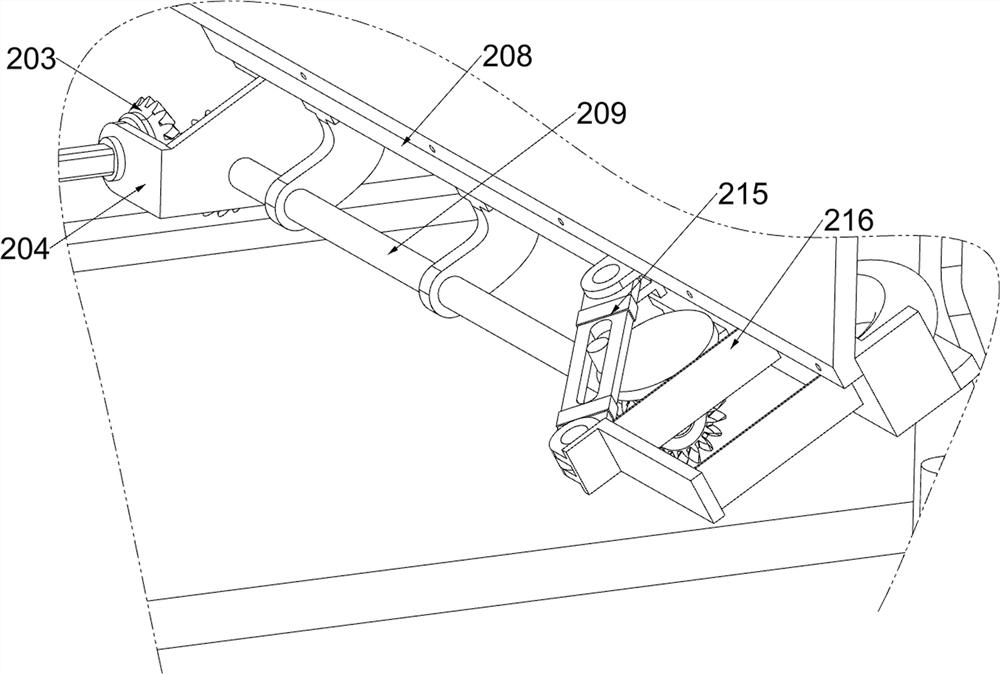
[0034] On the basis of Example 1, as Figure 1-10As shown, the automatic feeding unit includes a first motor 201, a spline shaft 202, a first bevel gear 203, a connecting frame 204, a first electric sliding rail 205, a first electric sliding block 206, a mounting plate 207, a U-shaped infeed The material rack 208, the first rotating shaft 209, the second bevel gear 210, the third bevel gear 211 and the feeding assembly; the upper rear part of the fixing plate 2 is bolted with the first motor 201; the upper rear part of the fixing plate 2 is rotated through the bracket A spline shaft 202 is connected; a first bevel gear 203 is fixedly connected to the shaft sleeve of the spline shaft 202; a first electric slide rail 205 is bolted on the inner and upper side of the support frame 3; Another first electric sliding rail 205 is connected with a common bolt; a first electric sliding block 206 is slidably connected to each of the two first electric sliding rails 205; a mounting plate ...


PUM


Abstract

The invention relates to the field of cold chains, in particular to a refrigeration equipment accessory integrated assembly unit for a cold chain. The technical problems that an existing copper pipe and U-shaped connector assembly process is tedious, the copper pipe is abraded, and the copper pipe is heated to deform are solved. According to the technical scheme, the integrated assembly unit for the refrigeration equipment accessories for the cold chain comprises a mounting base, a fixing plate and the like; the number of the mounting bases is four, and the upper sides of the four mounting bases are jointly and fixedly connected with a fixing plate. According to the U-shaped joint flaring device, a U-shaped joint is rapidly put into a copper pipe after the copper pipe is flared through the flaring rod, so that the copper pipe is in the state of being converted from softening during flaring to hardening after flaring, the U-shaped joint is put into the copper pipe, hard extrusion of the U-shaped joint to the copper pipe is avoided, manual work is replaced to guarantee that the U-shaped joint is vertically put into the copper pipe, and the work efficiency is improved. And the assembling quality of the U-shaped joint and the copper pipe is ensured.

Description

technical field [0001] The invention relates to the field of cold chain, in particular to an integrated assembly unit of refrigeration equipment accessories for cold chain. Background technique [0002] Evaporator is a kind of partition heat exchange equipment, which is used in refrigeration equipment such as cold storage. Its principle is that the low-temperature and low-pressure liquid refrigerant vaporizes and absorbs heat on one side of the heat transfer wall of the evaporator, so that the medium on the other side of the heat transfer wall is cooled, and the cooled medium is usually water or air. [0003] When assembling U-shaped joints between two adjacent copper tubes in the existing evaporator, the copper tubes need to be flared first, and then the U-shaped joints are manually inserted into the two copper tubes, and finally, the U-shaped joints are inserted into the two copper tubes by flame spray. The copper tube and the U-shaped joint are welded together, but becau...

Claims


Application Information

Patent Timeline
IPC IPC(8): B23P19/00B23K5/00B23K5/22
CPCB23P19/001B23P19/002B23P19/007B23K5/00B23K5/22
Inventor 李超
Owner 李超
Why Eureka
Try Eureka