Supercharge Your Innovation With Domain-Expert AI Agents!

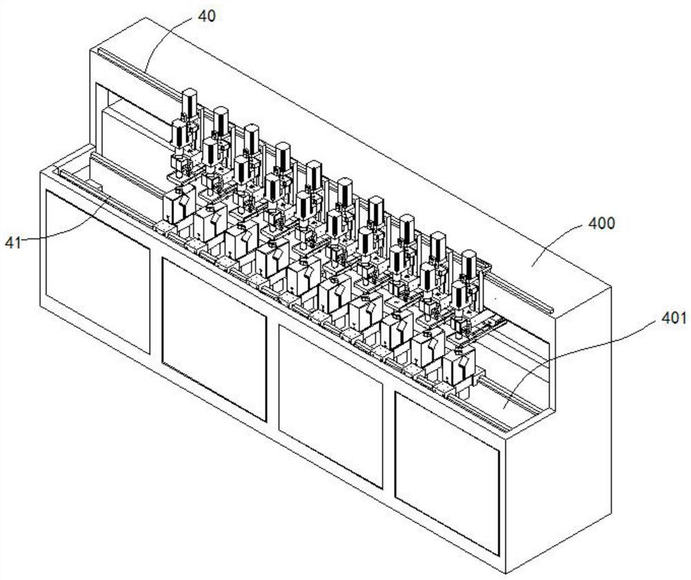
Water nozzle welding machine

A welding machine and faucet technology, which is applied in the welding field of pipe fittings, can solve the problems of pipeline systems that cannot meet the requirements of high-end industries, pipeline stagnant water and the influence of flow rate and flow, and pipeline welding is not firm, so as to eliminate potential safety hazards, solve shaking, The effect of ensuring welding quality

Pending Publication Date: 2022-06-17
深圳弘联硕科技有限公司
View PDF0 Cites 0 Cited by
  • Summary
  • Abstract
  • Description
  • Claims
  • Application Information

AI Technical Summary

Problems solved by technology

Correspondingly, the welding process requirements are more stringent. Due to the actual use requirements of the industry, there are very special requirements for many pipeline welding and process directions. For example, the traditional socket welding method causes protruding welding in the pipeline. Melt flow, so that there is stagnant water and the influence of flow rate and flow in the pipeline during operation and transportation
[0003] At present, when welding pipes and faucet fittings with a welding machine, the pipes and faucet fittings are first heated to melt the pipes and faucet fittings, and then the pipes and faucet fittings are butted, and the cooled pipes are glued to the faucet fittings. Finally, it is necessary to punch holes in the bonded pipe fittings to remove the remaining material; however, most of the existing technologies are manually socket welded by workers, which not only has high labor intensity and low production efficiency, but also easily leads to improper welding of pipelines. Strong, welding quality, unable to meet the needs of high-end industry piping systems

Method used


Image

  • Water nozzle welding machine
  • Water nozzle welding machine
  • Water nozzle welding machine

Examples


Embodiment Construction

[0031] The present invention will be described in detail below with reference to the accompanying drawings, and the technical solutions in the embodiments of the present invention will be described clearly and completely. Obviously, the described embodiments are only a part of the embodiments of the present invention, rather than all the embodiments. Based on the embodiments of the present invention, all other embodiments obtained by those of ordinary skill in the art without creative efforts shall fall within the protection scope of the present invention.

[0032] It should be noted that when a component is referred to as being "fixed to" another component, it can be directly on the other component or there may also be a centered component. When a component is considered to be "connected" to another component, it may be directly connected to the other component or there may be a co-existence of an intervening component. When a component is considered to be "set on" another co...


PUM


Abstract

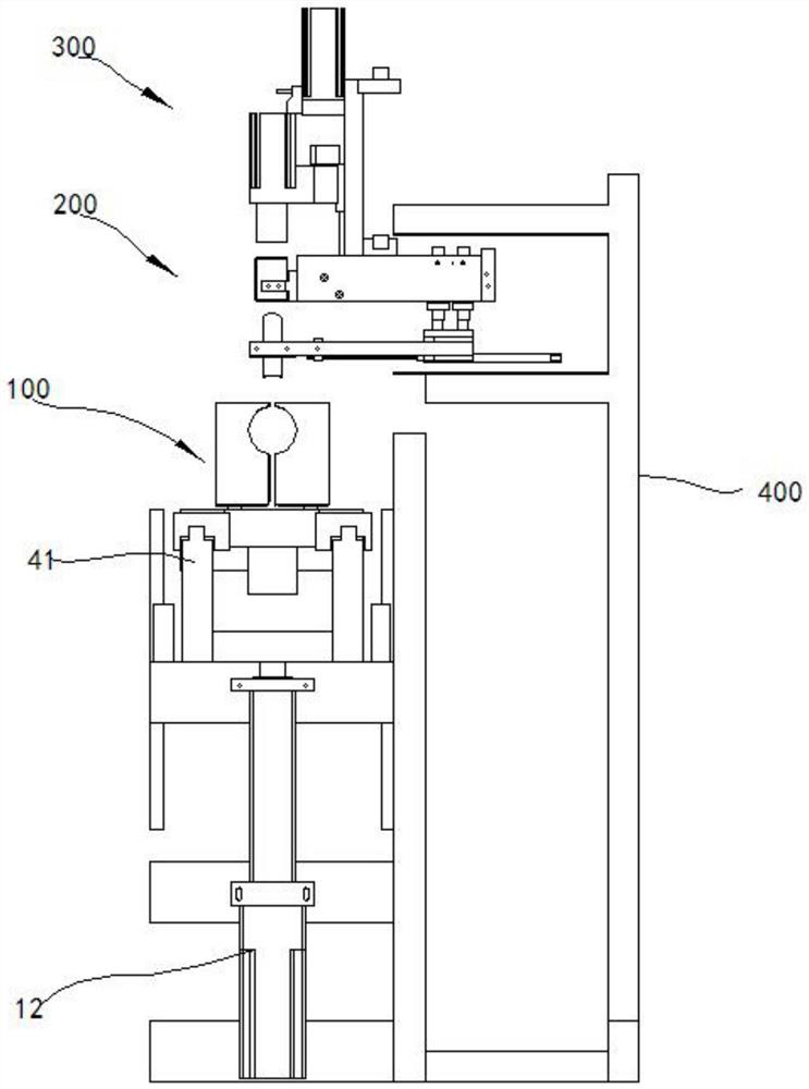
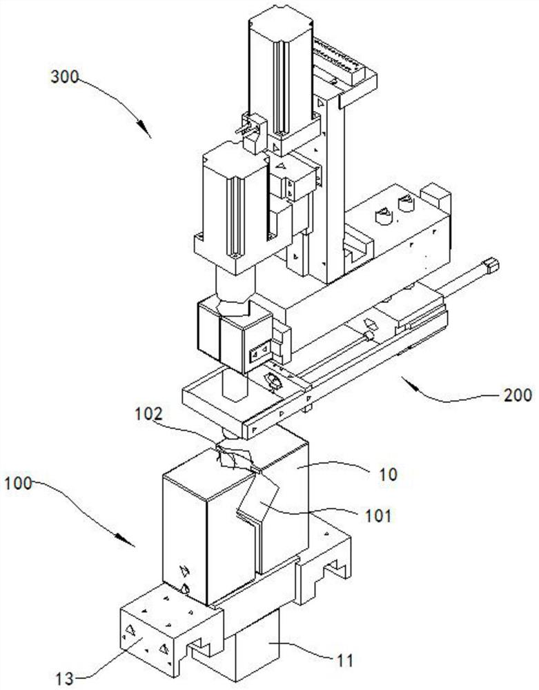
The water nozzle welding machine comprises a pipe clamping device, a heating device and a water nozzle fixing device, the pipe clamping device comprises lower clamping jaws, a lower execution part and a driving air cylinder, and a fixing hole and a welding hole are formed between the two lower clamping jaws; the heating device comprises a heating part, a floating part and a moving part, the heating part comprises a heating head and a fixed seat, the floating part comprises a floating seat, and a lifting structure is arranged on the floating seat; the moving part is connected with the heating part; the water nozzle fixing device comprises a drilling mechanism, a clamping jaw mechanism and a power source, the drilling mechanism comprises a drill bit and a drilling machine body, a protective sleeve is arranged on the drilling machine body, and the drill bit extends out of the protective sleeve; the clamping jaw mechanism comprises two upper clamping jaws and an upper execution part, and an upper clamping opening, a lower clamping opening and a through hole are formed between the two upper clamping jaws; the power source is used for driving the drilling mechanism to move, so that the protective sleeve extends into the upper clamping opening; according to the water nozzle welding machine, clamping, heating, welding and drilling are integrated, and the machining efficiency and the machining quality are guaranteed.

Description

technical field [0001] The present application relates to the technical field of welding of pipe fittings, in particular to a nozzle welding machine. Background technique [0002] In today's technologically developed industries, UHV substation transmission, data center server cooling system, battery energy storage industry, semiconductor chip ultra-pure water transportation, these industries have high requirements on the pipeline system, and higher requirements on the transportation system. . For example, in the selection of materials for ultrapure water, fluoropolymer pipes (such as PP, PVDF...) are usually used for the delivery pipelines of ultrapure water systems. Correspondingly, the welding process requirements are more stringent. Due to the actual use requirements of the industry, there are very special requirements for many pipeline welding and process directions, such as the traditional socket welding method, which makes the pipeline have protruding welding. Melt f...

Claims


Application Information

Patent Timeline
IPC IPC(8): B29C65/18B29C65/78B26F1/16
CPCB29C65/18B29C65/7858B29C66/522B26F1/16
Inventor 谭仕元
Owner 深圳弘联硕科技有限公司
Features
  • R&D
  • Intellectual Property
  • Life Sciences
  • Materials
  • Tech Scout
  • Unparalleled Data Quality
  • Higher Quality Content
  • 60% Fewer Hallucinations
Learn More