
Construction technology for large-depth semi-reverse excavation and steel pipe column inner supporting structure

A technology of construction technology and support structure, which is applied in basic structure engineering, excavation, construction, etc., can solve the problems of low utilization rate of support structure, long construction period, and waste of engineering materials, so as to reduce the number of installation and dismantling, improve construction efficiency, and dismantle Convenient and fast effect

Pending Publication Date: 2022-06-17
GUANGZHOU NO 1 CONSTR ENG +1
View PDF15 Cites 0 Cited by
  • Summary
  • Abstract
  • Description
  • Claims
  • Application Information

AI Technical Summary

Problems solved by technology

[0003] In the related technology, after the top is closed, the foundation pit is excavated layer by layer in the lower part of the project, and the brick slag needs to be backfilled, and it is also necessary to support the formwork, install the supporting structure, and reserve holes for the assembly and disassembly of the formwork. , the support structure is a temporary structure, which needs to be dismantled later, resulting in technical problems such as a long construction period, low utilization rate of the temporary support structure, and waste of engineering materials.

Method used


Image

  • Construction technology for large-depth semi-reverse excavation and steel pipe column inner supporting structure
  • Construction technology for large-depth semi-reverse excavation and steel pipe column inner supporting structure
  • Construction technology for large-depth semi-reverse excavation and steel pipe column inner supporting structure

Examples


Embodiment Construction

[0033] The technical solutions of the present invention will be clearly and completely described below with reference to the accompanying drawings. Obviously, the described embodiments are part of the embodiments of the present invention, but not all of the embodiments. Based on the embodiments of the present invention, all other embodiments obtained by those of ordinary skill in the art without creative efforts shall fall within the protection scope of the present invention.

[0034] In the description of the present invention, it should be noted that the terms "center", "upper", "lower", "left", "right", "vertical", "horizontal", "inner", "outer", etc. The indicated orientation or positional relationship is based on the orientation or positional relationship shown in the accompanying drawings, which is only for the convenience of describing the present invention and simplifying the description, rather than indicating or implying that the indicated device or element must have ...


PUM


Abstract

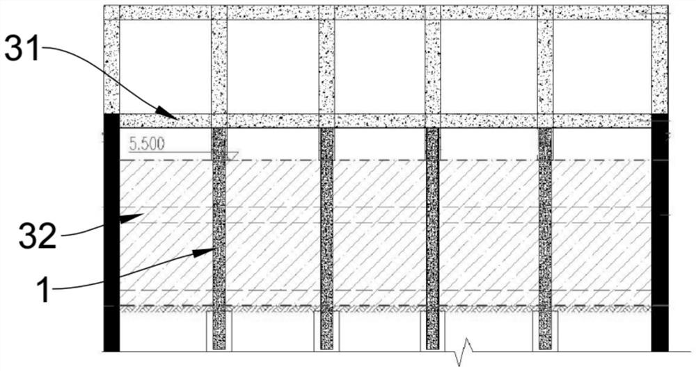
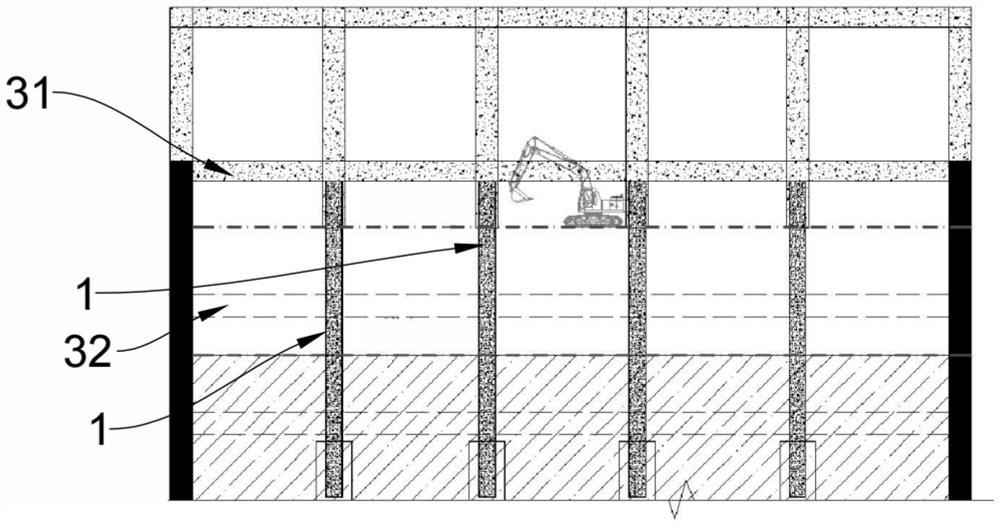
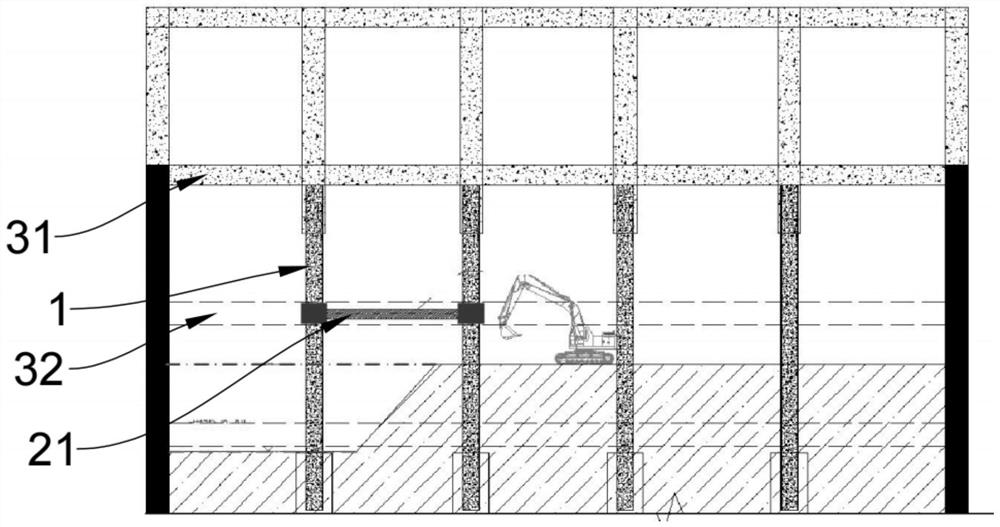
The invention relates to a construction process for large-depth semi-reverse excavation and a steel pipe column inner supporting structure, and the construction process comprises the following steps: S1, horizontally arranging first profile steel between two adjacent steel pipe columns on one side of a foundation pit, and excavating a soil body, located below a negative second structural layer, on the side, after excavation is conducted to the bottom face, a negative second structure layer is poured upwards to obtain a first beam body; s2, second profile steel is horizontally arranged between every two adjacent steel pipe columns on the other side of the foundation pit, a soil body, located below the negative second structural layer, on the side is excavated, and after excavation is conducted to the bottom face, the negative second structural layer is poured upwards to obtain a second beam body; and S3, third profile steel is horizontally arranged between every two adjacent steel pipe columns in the middle of the foundation pit, the soil body, located below the negative second structural layer, of the side is excavated, and after excavation is conducted to the bottom face, the negative second structural layer is poured upwards to obtain a third beam body. According to the technical scheme, the construction efficiency is greatly improved, the construction period is shortened, the utilization rate of the temporary supporting structure is improved, and waste of engineering materials is reduced.

Description

technical field [0001] The invention relates to the technical field of foundation pit excavation, in particular to a construction technique for large-depth semi-reverse excavation and an inner support structure of a steel pipe column. Background technique [0002] With the rapid development of the city and the development and utilization of underground space, the underground space is developed in a deeper direction, and the depth of the foundation pit is getting deeper and deeper. The new construction method adopted when the underground works need to cross obstacles such as roads and buildings is to excavate from the ground down to a certain depth, then close the top, and the rest of the lower works are constructed under the closed roof. , the construction method is cover and excavation method. [0003] In the related art, after the top is closed, the lower part is excavated layer-by-layer to dig deep foundation pits, and bricks and slag need to be backfilled, formwork supp...

Claims


Application Information

Patent Timeline
Patent Type & Authority Applications(China)
IPC IPC(8): E02D17/02E02D17/04
CPCE02D17/02E02D17/04
Inventor 张健李敏健黄志超潘正玉韩靖莫缵良李为吴昊钟裕弘罗瑛伍慧敏邓海力
Owner GUANGZHOU NO 1 CONSTR ENG
Learn More