Pulping machine shell machining method and pulping machine shell locating fixture

A technology for positioning fixtures and refiners, which is applied in the field of papermaking equipment, can solve the problems of affecting the processing accuracy, product processing quality, high labor intensity, and equipment utilization rate reduction, so as to shorten processing time, improve processing quality, and equipment utilization rate. Improved effect

Pending Publication Date: 2020-04-14
ZHENGZHOU YUNDA PAPER EQUIP
View PDF0 Cites 0 Cited by
  • Summary
  • Abstract
  • Description
  • Claims
  • Application Information

AI Technical Summary

Problems solved by technology

[0004] The mechanical processing of the refiner shell involves A1 end face processing, A2 end face processing, A3 end face processing, and A4 end face processing. It is necessary to process the bottom E6 end face and B5 end face. After processing, A1 holes need to be drilled and tapped, and A2 Hole and tap, drill A3 hole and tap, drill A4 hole and tap, and then bore D5 inner hole and D6 inner hole. Large and heavy, driving assistance is required for hoisting, turning and installation, and 2 people are required to cooperate with the operation, and it is installed on the workbench 3 times, and the machine tool utilization rate is low
For repeated disassembly, turning, clamping and positioning, the labor intensity is high, and the utilization rate of the equipment is greatly reduced.
Moreover, unreasonable clamping and positioning methods in the processing process will result in multiple processing benchmarks being set, resulting in the accumulation of processing errors and affecting the processing accuracy and product quality.

Method used


Image

  • Pulping machine shell machining method and pulping machine shell locating fixture
  • Pulping machine shell machining method and pulping machine shell locating fixture
  • Pulping machine shell machining method and pulping machine shell locating fixture

Examples


Embodiment Construction

[0037] The present invention will be further described below in conjunction with the accompanying drawings.

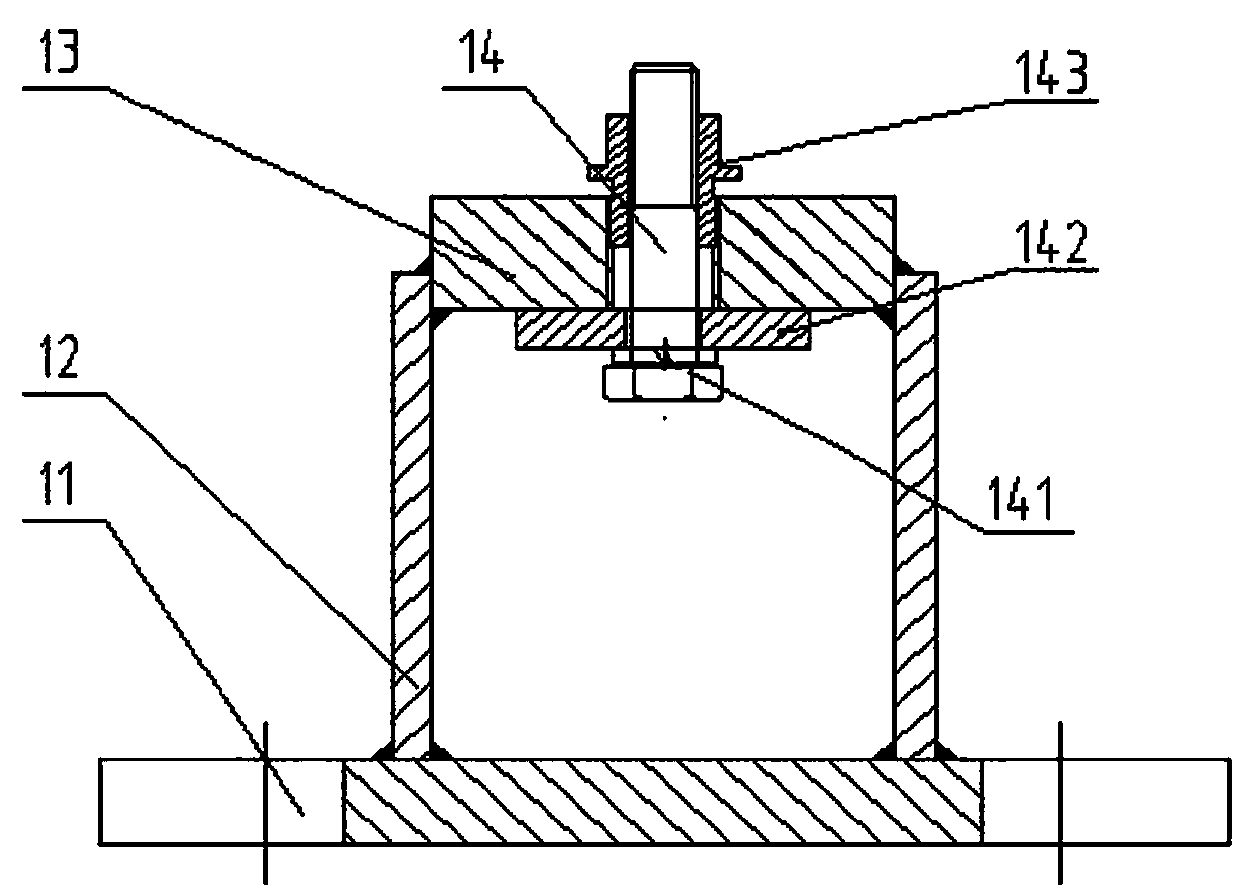
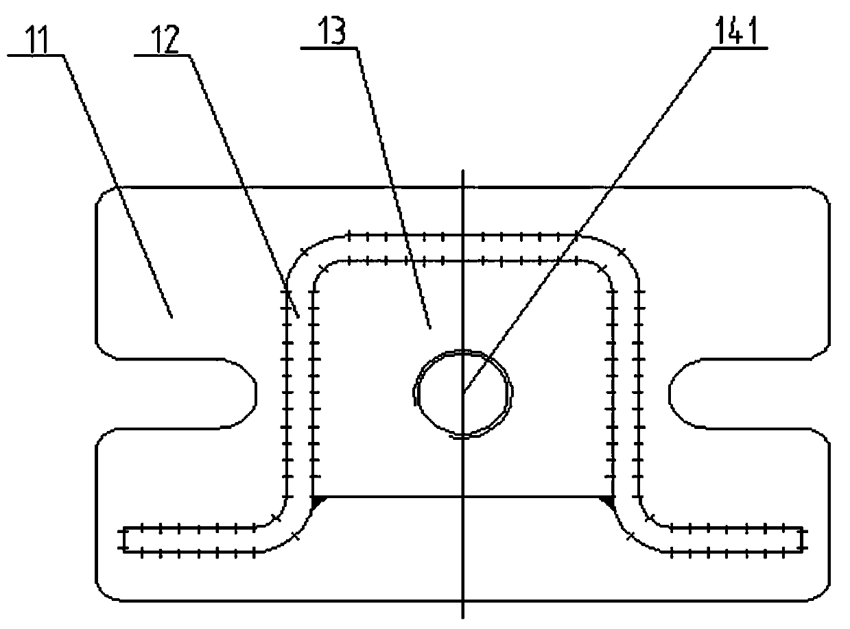
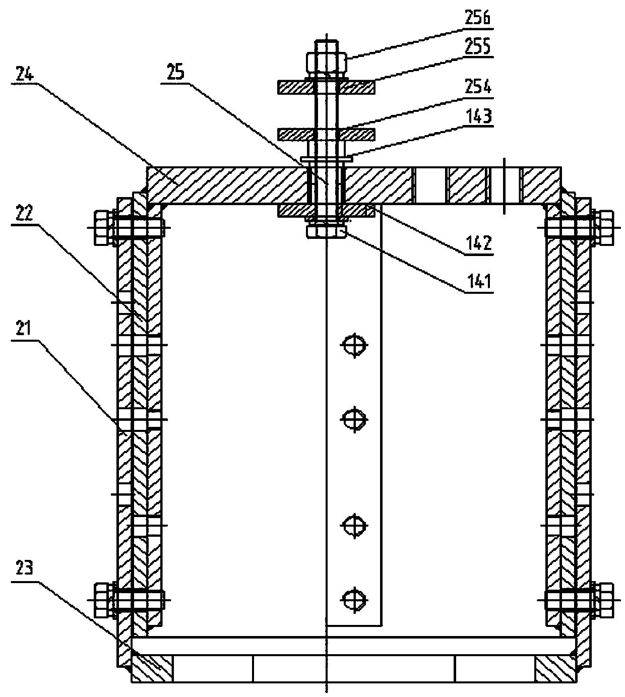
[0038] Such as Figure 1-7 As shown, in order to realize the positioning and clamping of the refiner shell, one clamping can realize the machining of multiple end surface structures, the present invention designs a positioning fixture for the refiner shell, including bottom tooling 1 and side tooling 2 , bottom tooling 1 is used for positioning the bottom surface of the refiner shell, side tooling 2 is used for positioning the side of the refiner shell, bottom tooling 1 and side tooling 2 cooperate to complete the positioning and clamping of the refiner shell .

[0039] For convenience of description, such as Figure 5-9 As shown, the end faces of the refiner shell of the workpiece to be processed are respectively set as A1 end face 41, A2 end face 42, A3 end face 43, A4 end face 44; B direction B5 end face 5; E direction E6 end face 6 , During the use of the refine...


PUM


Abstract

The invention discloses a pulping machine shell locating fixture comprising a bottom tool and a side tool. The bottom tool is used for locating the bottom face of a pulping machine shell. The side tool is used for locating the side face of the pulping machine shell. The bottom tool comprises a base and a bottom locating portion which is installed at the upper end of the base and used for locatingthe bottom face of the pulping machine shell. The side tool comprises a fixed seat and a moving seat which is arranged on the fixed seat and is in vertical movable fit with the fixed seat. The fixed seat and the moving seat achieve vertical movable fit through a moving mechanism. A fixing plate is connected to the upper end of the moving seat and provided with a side locating portion which is usedfor clamping the side face of the pulping machine shell. The pulping machine shell locating fixture can conduct locating and clamping on the bottom face and the side face of the pulping machine shelland achieve good locating of irregular structures, reduces the number of times of mounting, detaching and aligning of workpieces, lowers the work intensity of workers, improves the use efficiency ofa machine tool and shortens machining time.

Description

technical field [0001] The invention relates to the technical field of papermaking equipment, in particular to a machining method for a refiner shell and a positioning fixture. Background technique [0002] The refiner is a kind of continuous beating, because of its continuous beating, the beating quality is uniform and stable, and the efficiency is high. In the paper mill, the power refiner is not only used as beating equipment, but also used as pulp equipment, which makes the refiner widely used in paper mills. Therefore, the refiner has a broad market. Equipment manufacturers invest a lot of manpower, material and financial resources in the production of this type of equipment to improve the precision of equipment manufacturing to meet market demand. [0003] The traditional mechanical processing of the refiner shell is a one-station multi-process processing. The machining quality inspection of shell blanks checks the blanks and accepts them as qualified. Then the rel...

Claims


Application Information

Patent Timeline
Patent Type & Authority Applications(China)
IPC IPC(8): B23P23/02B23Q3/06
CPCB23P23/02B23Q3/062
Inventor 许银川刘伟杰许超峰许要锋
Owner ZHENGZHOU YUNDA PAPER EQUIP
Why Eureka
Try Eureka