Impact point deviation calculation method based on photoelectric reconnaissance equipment of unmanned helicopter

A technology of unmanned helicopters and photoelectric reconnaissance, which is applied in navigation calculation tools, navigation through speed/acceleration measurement, navigation, etc., can solve the problems of unguaranteed calculation accuracy and unguaranteed calculation accuracy, and achieve simple application and convenient operation , the effect of high calculation accuracy

Pending Publication Date: 2022-06-17
浙江航天润博测控技术有限公司
View PDF0 Cites 0 Cited by
  • Summary
  • Abstract
  • Description
  • Claims
  • Application Information

AI Technical Summary

Problems solved by technology

At present, the method of calculating the deviation is mostly to obtain the pixel deviation between the impact point position and the target position by freezing the current video image at the ground mission control seat, calculate the angle difference through the pixel deviation and the current sensor field of view value, and then calculate the deviation through coordinate conversion ; This method is suitable for the situation where the terrain fluctuation is not large (the target point and the impact point are at the same altitude), if the terrain fluctuation is large, the calculation accuracy cannot be guaranteed
Therefore, the existing technology has the problem that the calculation accuracy cannot be guaranteed for areas with large terrain fluctuations

Method used


Image

  • Impact point deviation calculation method based on photoelectric reconnaissance equipment of unmanned helicopter
  • Impact point deviation calculation method based on photoelectric reconnaissance equipment of unmanned helicopter
  • Impact point deviation calculation method based on photoelectric reconnaissance equipment of unmanned helicopter

Examples


Embodiment 1

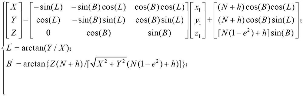
[0023] Example 1. The calculation method of impact point deviation based on unmanned helicopter photoelectric reconnaissance equipment includes the following steps:

[0024] The first step, initialization; the coordinates of the target in the geodetic Cartesian coordinate system (X a , Y a ,Z a ) and the coordinates of the impact point in the geocentric coordinate system (X b , Y b ,Z b ) is set to 0;

[0025] The second step is to judge whether the laser illuminator is performing ranging, if so, wait, if so, proceed to the third step;

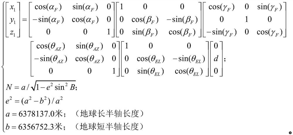
[0026] The third step is to collect the real-time data set (d,α of the laser illuminator at the current ranging point) F ,β F , γ F ,L,B,h,θ AZ ,θ EL ); where d is the slant distance value of the current ranging point output by the laser illuminator relative to the optoelectronic device, α F is the aircraft heading angle output by the inertial navigation system, β F The aircraft pitch angle output for the inertial navigation syste...

Embodiment 2

[0039]Example 2. The preferred embodiment of the present invention is used for photoelectric reconnaissance equipment on unmanned helicopters, and the photoelectric equipment includes visible light TV, infrared thermal imager, laser light meter, video tracker, photoelectric management computer, and servo system.

[0040] Visible light TV and infrared thermal imager are used to image the target, and the laser light meter is used to measure the slant distance value of the target relative to the optoelectronic device. The servo system collects the current azimuth and pitch angle of the optoelectronic device and transmits it to the optoelectronic management computer in real time.

[0041] The photoelectric management computer is the information processing center of the photoelectric detection equipment, receives the data sent by each unit in real time, and calculates the impact point deviation through the method proposed by the present invention.

[0042] When performing the task,...


PUM


Abstract

The invention discloses an impact point deviation calculation method based on photoelectric reconnaissance equipment of an unmanned helicopter. The impact point deviation calculation method comprises the following steps: step 1, initializing coordinates of a target in geodetic rectangular coordinates and coordinates of an impact point in a geocentric coordinate system; 2, judging whether the laser measuring and illuminating device performs distance measurement or not, and if so, performing the operation in the step 3; 3, collecting a data set of the laser measuring and illuminating device at the current distance measuring point in real time; 4, calculating the geodetic rectangular coordinates, the longitude value L'and the latitude value B 'of the current ranging point according to the data set acquired in the step 3; 5, judging a received ground task control equipment instruction, and storing a target coordinate and an impact point coordinate; and 6, calculating the distance deviation delta L and the deviation direction theta of the impact point relative to the target. The method has relatively high calculation precision in an area with relatively large terrain fluctuation.

Description

technical field [0001] The invention relates to an unmanned helicopter photoelectric reconnaissance device, in particular to a method for calculating the impact point deviation based on the unmanned helicopter photoelectric reconnaissance device. Background technique [0002] Unmanned helicopter photoelectric reconnaissance equipment is mainly used in battlefield reconnaissance, target positioning and tracking, fire guidance, and damage effect evaluation. Its combat mission is to carry out day and night reconnaissance, identification and tracking of targets, provide real-time reconnaissance images from the outside world, and conduct semi-active guided artillery rounds. The target indication guides the completion of the precision strike mission. This optoelectronic device includes visible light TV, infrared thermal imager, laser light meter, video tracker, servo control system, and optoelectronic management computer; visible light TV and infrared thermal imager are mainly use...

Claims


Application Information

Patent Timeline
Patent Type & Authority Applications(China)
IPC IPC(8): G01C21/16G01C21/20
CPCG01C21/1652G01C21/20
Inventor 贾子庆郑朋朋郝剑尹飞超唐长华魏振兴邵宏达麻斌鑫
Owner 浙江航天润博测控技术有限公司
Why Eureka
Try Eureka