Method for determining position of laser welding focus

A focus position, laser welding technology, applied in laser welding equipment, welding equipment, metal processing equipment, etc., can solve the problems of inaccurate reflection of laser energy density, inaccurate focus position selection, cumbersome focusing process, etc., to save image acquisition and processing time, avoiding the error of subjective judgment by the naked eye, and the effect of high image clarity

Pending Publication Date: 2022-06-24
苏州贝亚敏光电科技有限公司
View PDF0 Cites 0 Cited by
  • Summary
  • Abstract
  • Description
  • Claims
  • Application Information

AI Technical Summary

Problems solved by technology

[0004] There are at least the following defects in the determination method of the above-mentioned focal position: one, the image that this method requires collection has higher definition, therefore can spend a large amount of time on the focus of CCD camera, focus needs about 8s once, and the whole image acquisition processing process probably It takes 3 minutes, and the overall focusing process is cumbersome and time-consuming; 2. There is a big difference between the spot welding method and the actual welding, because the laser energy when the laser arc starts is significantly greater than the laser energy when it is working smoothly, so the weld formed by spot welding The diameter of the spot does not accurately reflect the energy density of the laser, resulting in inaccurate selection of the focus position; 3. During spot welding, spatter will inevitably be generated around the spot, causing the computer to make a wrong judgment on the diameter of the spot in the image

Method used


Image

  • Method for determining position of laser welding focus
  • Method for determining position of laser welding focus
  • Method for determining position of laser welding focus

Examples


Embodiment Construction

[0040] The preferred embodiments of the present invention will be described in detail below with reference to the accompanying drawings, so that the advantages and features of the present invention can be more easily understood by those skilled in the art.

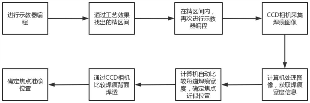
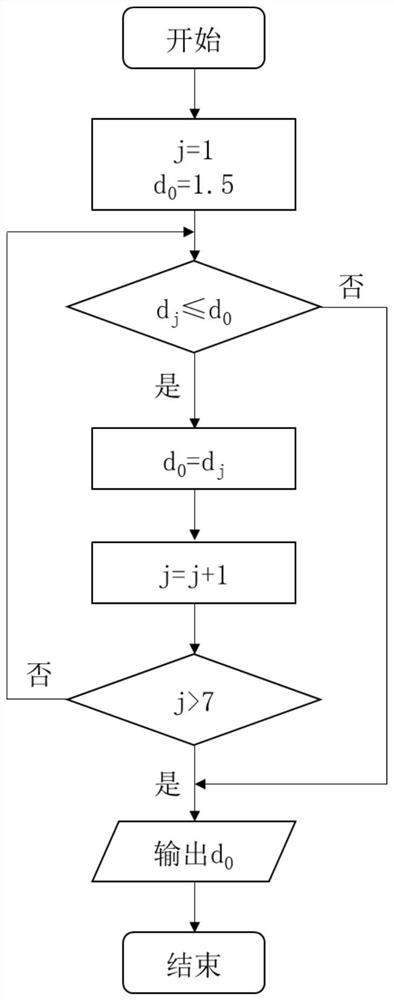
[0041] see figure 1 , 2 As shown, a method for determining the focus position of laser welding is used to determine the focus position of a laser head. This method is mainly used for laser welding equipment used for the first time. After the focus position is determined (with an error of less than 1mm), high-precision laser welding operations can be performed.

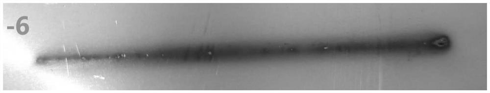
[0042] The basic principle of this method is: SUS304 stainless steel plate has an absorption rate of up to 95% of laser energy, and the laser head is controlled by a robotic arm to weld a weld mark with a length of about 5cm on the stainless steel, and the laser energy received at the starting point of the weld mark is the largest, The energy behind is stable, cl...


PUM

PropertyMeasurementUnit
thicknessaaaaaaaaaa
wavelengthaaaaaaaaaa

Abstract

The invention discloses a method for determining the position of a laser welding focus. The method comprises the following steps that S1, (2N + 1) test plates are prepared; s2, setting the power of a laser head as P1, setting the distance between the laser head and the ith test board as hi, starting the laser head, and controlling the laser head to weld a weld mark on the ith test board; repeating the step S2 for multiple times until i = 2N + 1; s3, the welding marks of the first back face, the second back face and the like are sequentially compared, and a focus precise interval [H1, HM] is obtained; s4, preparing M test plates; s5, the power of the laser head is set to be P2 and P2lt; p1, the distance between the laser head and the kth test plate is Hk, the laser head is started, and the laser head is controlled to weld a weld mark on the kth test plate; repeating the step S5 for multiple times until k is equal to M; and S6, comparing the welding marks on the kth test front side and the kth test back side to obtain the distance H0 between the laser head and the focus. According to the method for determining the position of the laser welding focus, the accuracy of the position of the focus is effectively ensured, and the rapidness of finding the focus is greatly ensured.

Description

technical field [0001] The invention relates to the technical field of laser processing, in particular to a method for determining the focus position of laser welding. Background technique [0002] In recent years, fiber laser welding has become the mainstream technology in the welding industry, and it is also widely used in precision fields such as the microelectronics industry and biomedicine. During laser welding, the laser head is driven by a moving mechanism such as a robotic arm, focuses the laser on the position of the workpiece to be welded, and moves at a preset speed and path to realize welding. The defocus amount of the laser is one of the main factors affecting the quality and accuracy of laser welding, so it is necessary to accurately find the focal position of the laser head. [0003] Generally, a red light indicator is provided on the laser head, which can indicate the approximate position of the focus. In order to accurately determine the focus position (wit...

Claims


Application Information

Patent Timeline
Patent Type & Authority Applications(China)
IPC IPC(8): B23K26/04
CPCB23K26/04
Inventor 王明娣王昊刘卫兵汤子麟陆文渊李祥李朋坤
Owner 苏州贝亚敏光电科技有限公司
Why Eureka
Try Eureka