Eureka AIR delivers breakthrough ideas for toughest innovation challenges, trusted by R&D personnel around the world.

Vacuum local heat treatment device and method for shaft workpieces

A technology for local heat treatment and shaft workpieces, applied in heat treatment furnaces, heat treatment equipment, measuring devices, etc., can solve problems such as the inability to guarantee the heating temperature of the workpiece, the influence of heat conduction on the structure and performance of the non-heated section of the workpiece, and thick oxide skin

Pending Publication Date: 2022-06-24
GUIZHOU SPACE APPLIANCE CO LTD
View PDF8 Cites 0 Cited by
  • Summary
  • Abstract
  • Description
  • Claims
  • Application Information

AI Technical Summary

Problems solved by technology

[0005] In the above-mentioned existing patented technology, the workpiece is heated in the air, and a thick oxide scale will be formed on the surface of the part, and the structure and performance of the non-heating section of the workpiece will be affected by the heat conduction of the heating section.
Therefore, the local induction heating heat treatment process of a simple electromagnetic induction machine is not effective, and the formed oxide skin will cause the product quality to be unqualified, or directly cause the workpiece to be scrapped
In addition, in the prior art, the heated workpiece can only be felt manually through the color of the heated workpiece, and the temperature of the workpiece cannot be quantified, resulting in the inability to guarantee the heating temperature of the workpiece

Method used


Image

  • Vacuum local heat treatment device and method for shaft workpieces
  • Vacuum local heat treatment device and method for shaft workpieces

Examples


Embodiment Construction

[0038] The technical solutions in the embodiments of the present invention will be clearly and completely described below with reference to the accompanying drawings in the embodiments of the present invention. Obviously, the described embodiments are only a part of the embodiments of the present invention, not all of the embodiments. Based on the embodiments of the present invention, all other embodiments obtained by those of ordinary skill in the art without creative efforts shall fall within the protection scope of the present invention.

[0039] It should be noted that all directional indications (such as up, down, left, right, front, back, etc.) in the embodiments of the present invention are only used to explain the relationship between various components under a certain posture (as shown in the accompanying drawings). The relative positional relationship, the movement situation, etc., if the specific posture changes, the directional indication also changes accordingly. ...


PUM


Abstract

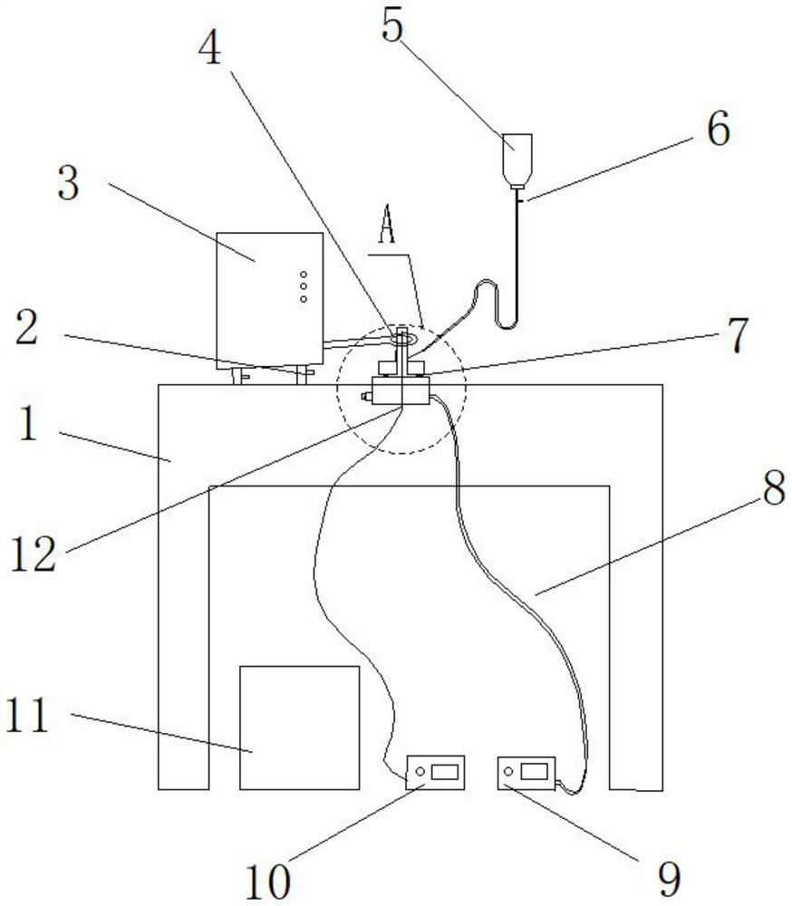
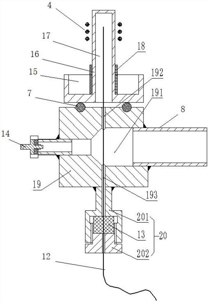
A vacuum local heat treatment device for shaft workpieces comprises a temperature display device and an electric induction high-frequency heating machine arranged on a workbench. A containing cavity is formed in the protection cover shell and used for containing the shaft workpiece needing to be heated; the vacuum generator assembly is connected with the protective cover shell and used for vacuumizing the containing cavity of the protective cover shell; the temperature sensor is used for sensing the temperature of the accommodating cavity and is connected with the temperature display device; the quenching tank is arranged at the position close to the workbench; an annular groove is formed in the lower portion of the protective cover shell, and a cooling medium is contained in the annular groove. And an induction coil of the electric induction high-frequency heating machine is sleeved on the upper part of the protective housing. The heat treatment device provided by the invention can be used for creating a vacuum environment during local heating of shafts and displaying the temperature of a heating section, so that a non-heating section is protected during local heating of the shaft workpieces, and the heating section does not generate oxide skin by utilizing the vacuum environment.

Description

technical field [0001] The invention relates to the technical field of heat treatment of shaft workpieces, in particular to a vacuum partial heat treatment device and method for shaft workpieces. Background technique [0002] The shaft metal workpiece used on the connector has different mechanical properties in different parts of the workpiece, and after heat treatment, the surface is not allowed to be oxidized. Therefore, it is necessary to perform local heat treatment on the parts to change the organizational structure of different sections of the workpiece to meet the requirements of its use. At this stage, the electric induction high-frequency machine is commonly used in the industry to locally heat the metal workpiece. The principle is to use the principle of electromagnetic induction to generate a high-density induced current on the surface of the metal workpiece to rapidly heat it. [0003] For example, the patent with the application number CN201820716733.9 disclose...

Claims


Application Information

Patent Timeline
Patent Type & Authority Applications(China)
IPC IPC(8): C21D9/28C21D1/773C21D1/10C21D1/63C21D1/26G01K7/02G01K1/14
CPCC21D9/28C21D1/773C21D1/10C21D1/63C21D1/26G01K7/02G01K1/14C21D2221/00Y02P10/25
Inventor 曹先铭何浩
Owner GUIZHOU SPACE APPLIANCE CO LTD
Why Eureka
Eureka Blog
Learn More