Eye movement tracking optical device, head-mounted display device and eye movement tracking method

An eye-tracking and optical device technology, applied in optics, optical components, instruments, etc., can solve problems affecting the accuracy of eye-movement interaction, inaccurate eye tracking, and loss, so as to improve shooting quality, avoid interference, and improve The effect of accuracy

Pending Publication Date: 2022-06-24
TAPUYIHAI SHANGHAI INTELLIGENT TECH CO LTD
View PDF0 Cites 0 Cited by
  • Summary
  • Abstract
  • Description
  • Claims
  • Application Information

AI Technical Summary

Problems solved by technology

[0003] The existing eye tracking interaction methods mostly use the off-axis tracking of the camera and the eyeball, which will cause tracking distortion in the opposite direction of the off-axis angle, which will easily lead to inaccurate or even lost eye tracking, affecting the accuracy of eye movement interaction

Method used


Image

  • Eye movement tracking optical device, head-mounted display device and eye movement tracking method
  • Eye movement tracking optical device, head-mounted display device and eye movement tracking method
  • Eye movement tracking optical device, head-mounted display device and eye movement tracking method

Examples


Embodiment 1

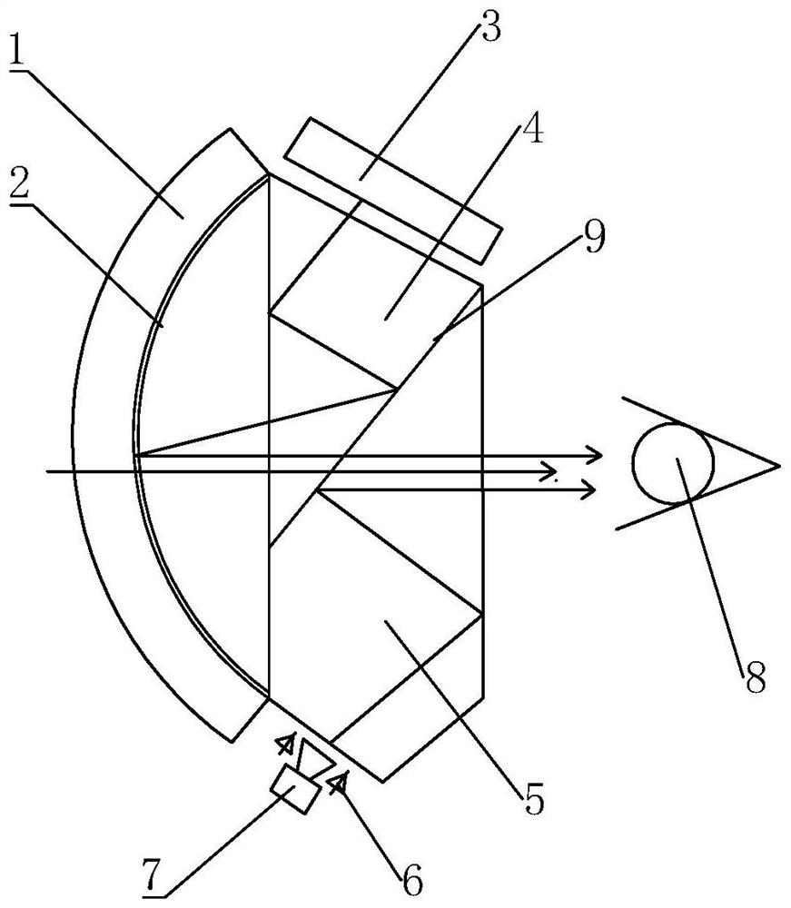
[0043] An eye-tracking optical device such as figure 1 As shown, it includes an optical assembly, a display screen 3 at the top of the optical assembly, and a camera 7 at the bottom of the optical assembly. The optical assembly includes a first lens 1 and a second lens arranged side by side. The first lens 1 is a uniformly thick curved lens with a convex surface and a concave surface. The concave surface is close to the second lens. Semi-reflective film 2. The second lens is a waveguide lens, and the waveguide lens includes a waveguide prism 4 and a waveguide compensation mirror 5. The waveguide prism 4 is located above and close to the display screen, and the waveguide compensation mirror 5 is located below and close to the camera. The waveguide prism 4 and the waveguide compensating mirror 5 are bonded together along a slope from upper right to lower left to form a uniform optical lens, and a second semi-transparent and semi-reflective film 9 is pasted at the bonding positi...

Embodiment 2

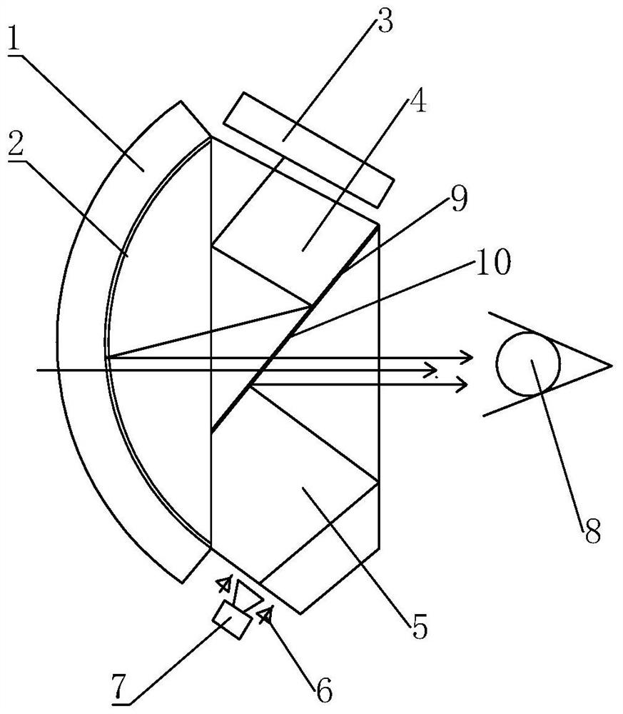
[0045] An eye-tracking optical device such as figure 2 As shown, on the basis of Embodiment 1, an infrared reflective film 10 is added at the boundary between the waveguide prism and the waveguide compensation mirror to reduce the loss of infrared light, improve the reflectivity of infrared light, and improve the clarity of the eye image captured by the camera. .

Embodiment 3

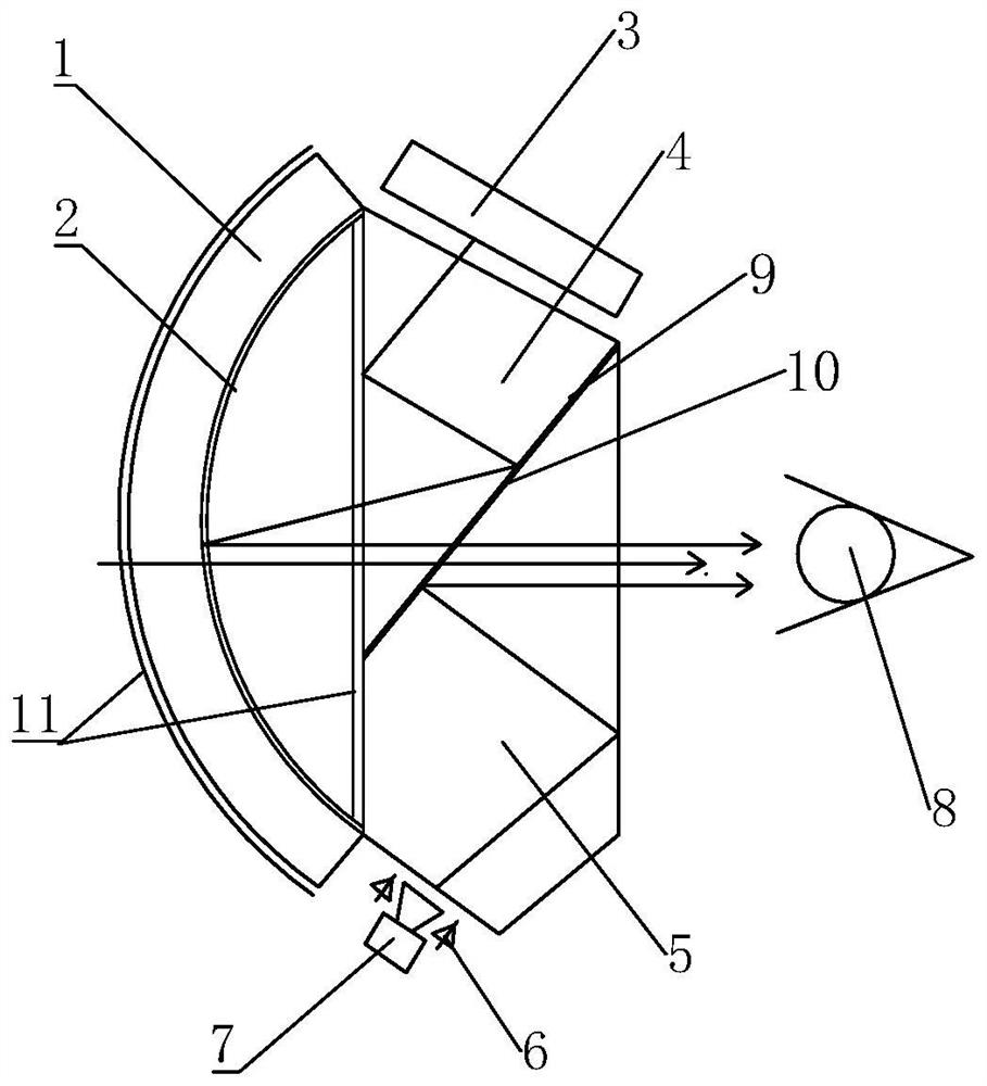
[0047] An eye-tracking optical device such as image 3 As shown, on the basis of Embodiment 2, a layer of infrared cut-off glass 11 is respectively arranged on the front side and the rear side of the first lens to filter out the infrared light in the external ambient light, prevent the camera from overexposure, and affect the shooting picture. quality.


PUM


Abstract

The invention relates to the field of head-mounted display equipment, in particular to an eye movement tracking optical device, head-mounted display equipment applying the eye movement tracking optical device and an eye movement tracking method. An eye movement tracking optical device comprises an optical assembly, a display screen, a camera and an infrared emitter, the optical assembly comprises a first lens and a second lens which are arranged side by side, one side, close to the second lens, of the first lens is provided with a concave surface, and the concave surface is provided with a first part reflector; the second lens is a waveguide lens, a second partial reflector is arranged in the middle of the waveguide lens, the display screen is located above the waveguide lens, and the camera is located below the waveguide lens and used for shooting images of eyes. According to the invention, the waveguide lens, the concave lens and the partial reflector are utilized to form an optical assembly, so that the light of the display screen and the light of the infrared emitter can be emitted into human eyes in parallel, thereby realizing coaxial tracking shooting of eye images by a camera, and improving the accuracy of eye tracking.

Description

technical field [0001] The present invention relates to the field of head-mounted display devices, in particular to an eye-tracking optical device, a head-mounted display device using the same, and an eye-tracking method. Background technique [0002] In the fields of virtual reality (VR) and mixed reality (AR), human-computer interaction design has always been the top priority of research in this field. At present, common human-computer interaction methods include both physical contact interactions such as handles, remote controls, and touchpads, as well as non-physical contact interactions such as gesture recognition, eye tracking, and motion capture. Eye tracking technology is to judge the real gaze point of the human eye by detecting the position of the pupil of the human eye, so as to control the image display effect of the head-mounted display device. Compared with other interaction methods, the eye-tracking interaction method is more suitable for natural interaction,...

Claims


Application Information

Patent Timeline
Patent Type & Authority Applications(China)
IPC IPC(8): G02B27/00G02B27/01
CPCG02B27/0093G02B27/0172G02B27/0179G02B2027/0187
Inventor 卫荣杰
Owner TAPUYIHAI SHANGHAI INTELLIGENT TECH CO LTD
Why Eureka
Try Eureka