Optimization method for improving injection molding precision of optical element

A technology of optical components and optimization methods, applied in design optimization/simulation, data processing applications, predictions, etc., can solve problems such as high processing costs, limited effect of improving the quality of injection molded parts, and low efficiency

Pending Publication Date: 2022-06-24
GUANGDONG UNIV OF TECH
View PDF0 Cites 0 Cited by
  • Summary
  • Abstract
  • Description
  • Claims
  • Application Information

AI Technical Summary

Problems solved by technology

This method of excessively demanding the surface quality of the mold core will cause low efficiency and high processing costs,...

Method used


Image

  • Optimization method for improving injection molding precision of optical element
  • Optimization method for improving injection molding precision of optical element

Examples


Embodiment Construction

[0037] The technical solutions in the embodiments of the present invention will be clearly and completely described below with reference to the accompanying drawings in the embodiments of the present invention. Obviously, the described embodiments are only a part of the embodiments of the present invention, but not all of the embodiments. Based on the embodiments of the present invention, all other embodiments obtained by those of ordinary skill in the art without creative efforts shall fall within the protection scope of the present invention.

[0038] The purpose of the present invention is to provide an optimization method for improving the injection molding precision of optical components, so as to solve the problems existing in the prior art.

[0039] In order to make the above objects, features and advantages of the present invention more clearly understood, the present invention will be described in further detail below with reference to the accompanying drawings and speci...


PUM


Abstract

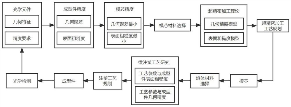
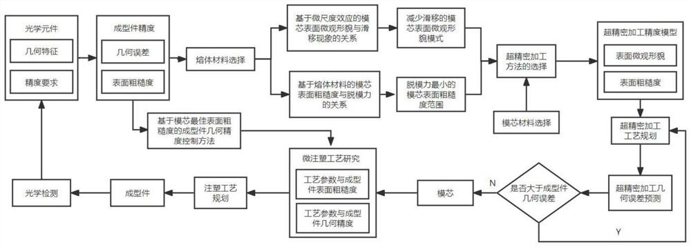
The invention discloses an optimization method for improving the injection molding precision of an optical element, which provides an injection molding process considering melt materials and mold core surface roughness on the premise that injection molding process parameters and the like are all optimal, selects different mold core surface roughness intervals according to different melt materials, and predicts the injection molding precision of the optical element on the basis of an existing ultra-precision machining quality prediction model. Compared with the extremely high quality requirement for the surface of the mold core in a traditional method, the optimization method for improving the injection molding precision of the optical element improves the molding precision of the optical element and reduces the surface roughness of the optical element on the basis of improving the machining efficiency of the mold core; and optimization of a micro injection molding process of the optical element and improvement of the optical performance of the element are facilitated.

Description

technical field [0001] The invention relates to the technical field of micro-injection molding, in particular to an optimization method for improving the injection precision of optical components. Background technique [0002] At present, micro-injection molding technology: through more advanced equipment, the process parameters, environmental variables and dimensional control are strictly controlled to process optical components with high surface quality (surface roughness, shape accuracy) and optical properties. The biggest feature is that the injection volume is small, the geometric dimensions of the mold core and the molded part are small, the parameter control of the injection molding process is relatively high, and the quality of the mold core is relatively high. [0003] Now the research on micro-injection mainly stays on the exploration of its injection molding process, such as injection speed, melt temperature, holding pressure, mold temperature, holding time, etc. ...

Claims


Application Information

Patent Timeline
IPC IPC(8): G06F30/10G06F30/20G06Q10/04
CPCG06F30/10G06F30/20G06Q10/04
Inventor 王素娟李晓蓬谢海振孙占文王海龙
Owner GUANGDONG UNIV OF TECH
Why Eureka
Try Eureka