
Semiconductor power device reliability detection box and detection method

A technology for power devices and detection methods, which is applied in the fields of instruments, electrical measurement, short-circuit testing, etc., can solve the problems of lack of theory, detection methods, and methods of impurity ion evaluation, and achieve simple experimental methods and on-site practicality. Good, cost-effective results

Inactive Publication Date: 2022-06-28
陕西半导体先导技术中心有限公司
View PDF9 Cites 1 Cited by
  • Summary
  • Abstract
  • Description
  • Claims
  • Application Information

AI Technical Summary

Problems solved by technology

[0004] During the packaging process, if the epoxy material and the thermally conductive filler are contaminated by Na, K, Ca, Mg, Fe, Cu, Cr, Ni, Cl, S, Br and other inorganic and organic substances, during the packaging process, these ions Or atoms (or molecules) will form deposition areas on the surface and sides of the chip as the process progresses, which will affect the electrical parameters of the semiconductor chip and its temperature (environmental) stability to a certain extent. How to evaluate the purity of packaging materials for power device characteristics and reliability, and there is also a lack of corresponding methods
[0005] Due to the lack of methods for evaluating the characteristics of power devices due to the lack of voids and delaminations between epoxy resins and their thermally conductive fillers and semiconductor chips after curing, there is also a lack of theory and testing for evaluating the characteristics of power devices based on the content and distribution of impurity ions in epoxy resins. method, therefore, it is impossible to obtain the specific quantitative relationship of how impurity elements affect semiconductor power devices, and because voids, separation layers and these impurity elements do have an impact on semiconductor chips, one or several methods of how to evaluate this impact are developed. become an urgent technical problem to be solved

Method used


Image

  • Semiconductor power device reliability detection box and detection method
  • Semiconductor power device reliability detection box and detection method
  • Semiconductor power device reliability detection box and detection method

Examples


Embodiment Construction

[0032] In view of the above technical solutions, preferred embodiments are now given and described in detail with reference to the drawings.

[0033] The semiconductor power device 100 of the present invention is: the drain-source reverse biasing and gate-source reverse biasing of various power MOSFETs; the collector-emitter or emitter-base reverse biasing of various bipolar transistors; The gate of the junction FET is sophisticated in reverse bias; the diode is reverse biased.

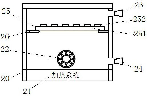
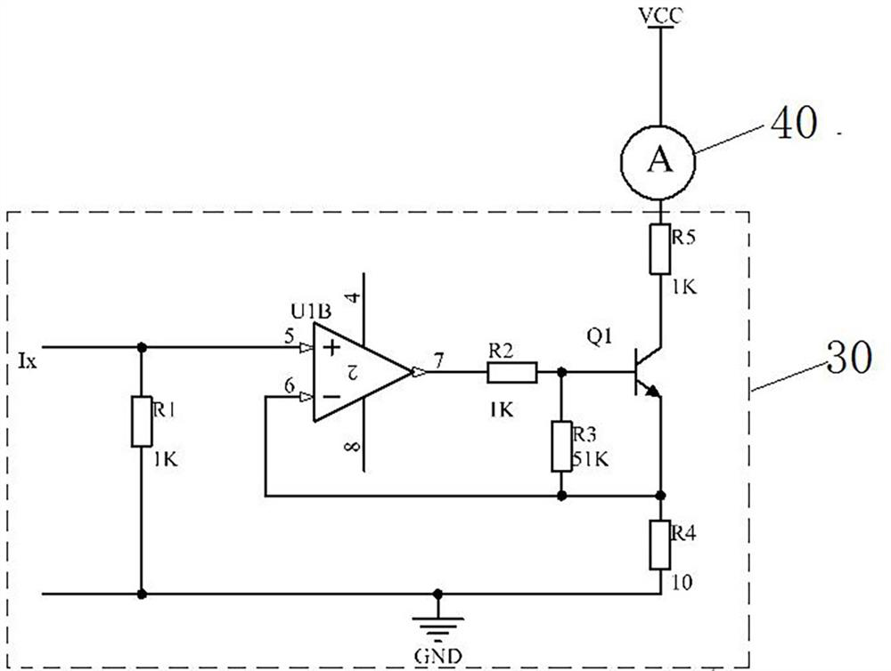
[0034] The reliability test box can be obtained commercially. Its general structure is, see figure 1 , including an openable and closable box 20 with a door, and a heating system 21 is arranged at the bottom of the box 20 to heat the box, see the circuit diagram of the heating system Figure 4 , adjust the temperature inside the box. The heating system 21 also includes a heat soaking fan 22 arranged in the box body to make the temperature inside the box body uniform. A block 23 for the hot air out...


PUM


Abstract

The invention discloses a semiconductor power device reliability detection box and a detection method. The reliability detection box comprises a reliability adaptation plate, a heating system and a control system. The power device is placed on the reliability adapter plate for experiment, and the heating system provides the required detection temperature; the control system is used for controlling the temperature change of the heating system, carrying out temperature change cyclic detection and monitoring the leakage current in the detection process; and when the leakage current of the power device exceeds the standard, the control system cuts off the power supply of the power device with the leakage current exceeding the standard and displays a power device holder code. The method is easy to implement, high in detection reliability and low in detection cost.

Description

technical field [0001] The invention relates to the technical field of semiconductor power devices and power electronics, in particular to a reliability detection method for reducing the failure rate of a plastic encapsulated semiconductor power device on-board. Background technique [0002] Plastic-encapsulated semiconductor power devices are the most widely used electronic power devices. In order to ensure the quality of various plastic-encapsulated semiconductor power devices, a variety of specific quality inspections and inspections are proposed according to the manufacturing process characteristics, material characteristics and application environment of semiconductor power devices. Methods and corresponding test standards, such as GJB548B, GJB7400-2011, GJB33A, etc. are typical. As a method for judging the quality of plastic-encapsulated power devices, for example, during temperature shock testing, the temperature environment and power supply voltage of the power devic...

Claims


Application Information

Patent Timeline
Patent Type & Authority Applications(China)
IPC IPC(8): G01R31/00G01R31/52G01R1/04
CPCG01R31/00G01R31/52G01R1/04
Inventor 温灵生何晓宁刘兴
Owner 陕西半导体先导技术中心有限公司
Learn More