
Semiconductor structure and manufacturing method

A technology of semiconductor and layer structure, applied in the direction of semiconductor devices, electrical solid devices, electrical components, etc., can solve the problems of lower production efficiency, insufficient coupling rate, and insufficient dielectric film area, so as to improve coupling rate and reliability sexual effect

Pending Publication Date: 2022-06-28
INST OF MICROELECTRONICS CHINESE ACAD OF SCI +1
View PDF0 Cites 0 Cited by
  • Summary
  • Abstract
  • Description
  • Claims
  • Application Information

AI Technical Summary

Problems solved by technology

The area of ​​the dielectric film in the prior art is not large enough, resulting in a low coupling rate. Now the coupling rate is mainly improved by changing the gate structure. The disadvantage is that many process steps need to be added, so the production efficiency is reduced, and it is difficult to apply to Actual Production

Method used

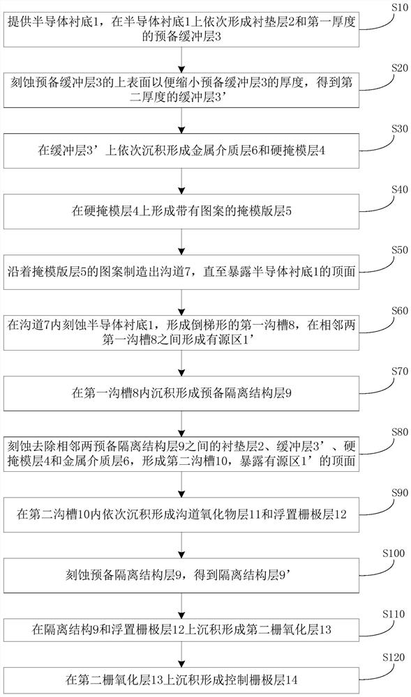
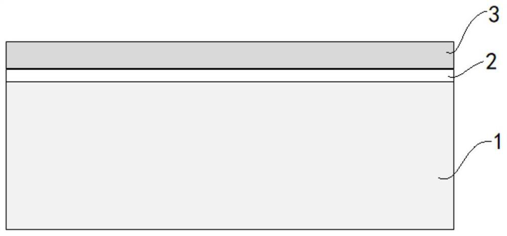

Image

  • Semiconductor structure and manufacturing method
  • Semiconductor structure and manufacturing method
  • Semiconductor structure and manufacturing method

Examples


Embodiment Construction

[0036] Hereinafter, embodiments of the present disclosure will be described with reference to the accompanying drawings. It should be understood, however, that these descriptions are exemplary only, and are not intended to limit the scope of the present disclosure. Also, in the following description, descriptions of well-known structures and techniques are omitted to avoid unnecessarily obscuring the concepts of the present disclosure.

[0037] Various structural schematic diagrams according to embodiments of the present disclosure are shown in the accompanying drawings. The figures are not to scale, some details have been exaggerated for clarity, and some details may have been omitted. The shapes of the various regions and layers shown in the figures, as well as their relative sizes and positional relationships are only exemplary, and in practice, there may be deviations due to manufacturing tolerances or technical limitations, and those skilled in the art should Regions / la...


PUM


Abstract

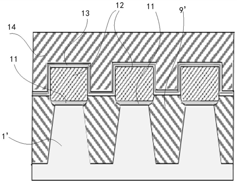
The invention discloses a semiconductor structure and a manufacturing method. The semiconductor structure includes: an active region; the two isolation structures are located on the two sides of the active region respectively; the first gate oxide layer is located on the active region; the floating gate layer is located on the first gate oxide layer; the second gate oxide layer covers the isolation structure and the floating gate layer; and the control gate layer covers the second gate oxide layer. According to the semiconductor structure provided by the embodiment of the invention, the structure of the floating gate is unchanged compared with the prior art, and the area of the second gate oxide layer is larger, so that the coupling rate is higher and the electric quantity loss is small during use, and the reliability of the storage device is improved.

Description

technical field [0001] The present application relates to the field of semiconductor technology, and in particular, to a semiconductor structure and a manufacturing method. Background technique [0002] Flash memory devices allow electrons to enter and exit the floating gate by applying an appropriate voltage to the control gate. The function of the dielectric film is to transmit the voltage applied to the control gate to the floating gate, and the voltage loss transmitted to the floating gate is smaller. It shows that the electrical characteristics are better. If the voltage delivered to the floating gate is larger, the coupling ratio can be improved and the power loss can be reduced. The area of ​​the dielectric film in the prior art is not large enough, resulting in an insufficient coupling rate. Now, the coupling rate is mainly improved by changing the gate structure. Actual Production. SUMMARY OF THE INVENTION [0003] The purpose of this application is to provide ...

Claims


Application Information

Patent Timeline
IPC IPC(8): H01L27/11521
CPCH10B41/30
Inventor 申相旭李俊杰周娜王佳李琳
Owner INST OF MICROELECTRONICS CHINESE ACAD OF SCI
Learn More